Part 8
DISCONNECTING ALL CABLES
After removal of the cable cover, the connector area will be accessible
then. Please
first note orientations of every existing cable connection
and
then disconnect every cable properly before separating the main unit from the
adjustable stand assembly. Please note that the click lock spring has to be
pressed down prior to pulling out the connector such as the LAN port or the
CR port or the alternate RJ45 form COM3 port. Please also note that the fixing
screws have to be loosened free prior to disconnection such as the 2 regular
DB9 form COM ports or the VGA port. Please
always hold the connector
head
instead of pulling on the cable wire when disconnecting any connector.
Failure to do this could damage the cable and jack that is considered as an
artificial destruction. Damages due to incorrect disconnection operation
are not covered by product warranty!
SEPARATING MAIN UNIT
In order to settle the touch terminal properly in a point of sale system,
all the cable connections have to be routed through its base, either slim or
universal. Therefore, please observe the procedures from A to C below to
separate the main unit from the slim base stand assembly after all cables in
cable cover disconnected.
Step A:
Prepare a soft clean flat surface, such as
a piece of cloth on the desk to seat the
front surface of main unit
Step B:
Press the Lock/Release button for main
unit detach and meantime ...
Step C:
Slide the base stand assembly to left to
separate the main unit from base stand
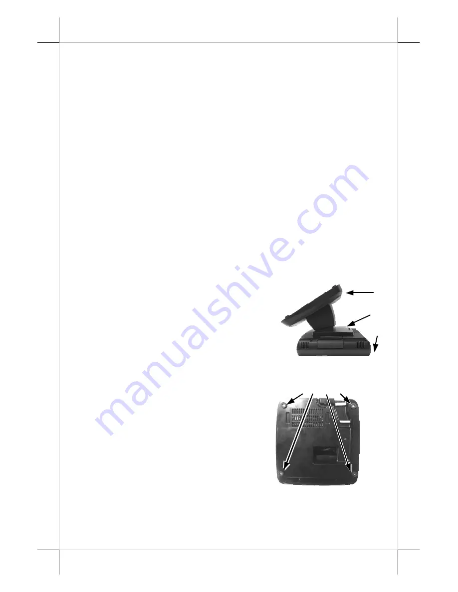
OPENING STAND ASSEMBLY
Take the adjustable stand assembly and
turn it up side down to show the bottom of the
base. Remove the bottom plate fixing screws in
rubber feet to open the bottom plate as in the
picture at the right.
The inside of an example base will look
like the picture below with numbered items
listed. However, there could be some variation
to the contents inside depending on what option
items actually installed.
Fixing Screws
Base bottom
C
A
B


