Hardware Configuration
ROBO-8712E Series User’s Manual
2-3
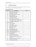
2.2
Connector Allocation
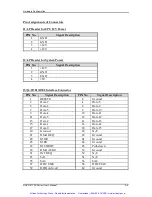
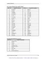
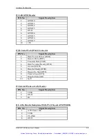
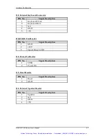
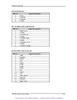
I/O peripheral devices and flash disk are connected to the interface connectors and
DOC socket on this single board computer (Figure 2-1)
Connector Function List
Connector
Description
Remark
J1
4P Header for CPU 12V Power
J2
4P Header for System Power
J3
IDE1 Interface Connector
J4
PS/2 Keyboard/Mouse Connector
J5
8-Bit GPIO Header
J6
IDE2 Interface Connector
J7
Serial Port-1 Connector
J8
Serial Port-2 Connector
J9
External Wake on LAN Header
J11
4 Pin Header Backplane 5VSB, PS_ON, and
ATX PWROK PS_ON, and ATX PWROK
J12
External Keyboard Connector
J13/J33/J34
Fan Header
J14
Power On Header
J15
Reset Header
J16
External Speaker Header
J17
Keyboard Lock Header
J18
HDD LED Header
J19
IR Header
J20
External SMBus Header
J21/J23
Bracket Side USB Connector
J22/J26
Ethernet Link LED Header
J24/J25
Ethernet RJ-45 Interface Connector
J27/J28
2 Port USB Header
J29
CD-IN Header
J30
D-SUB 15 VGA Connector
J31
On-Board AC97 Audio Header
J32
Mobile Pentium 4/Northwood (Prescott)
Selection
J37
Compact Flash Socket on IDE1 Master
J38
FDC Interface Connector
J39
Printer Interface Connector
Artisan Technology Group - Quality Instrumentation ... Guaranteed | (888) 88-SOURCE | www.artisantg.com


