POSITIONING
THE POCKET CUT
It is recommended
that a minimum of
two pocket cuts be used at each joint.
The
pocket cuts
can be positioned on the workpiece using one of the three
methods
described
below.
The base
of
the
Cutter
is
ribbed.
These
ribs
are located
so that they
can
be used as alignment guides to help position the
work
to
the
cutter.
A
scale
on
the
base of
the
Pocket Cutter
indicates
the ribs recommended
for locating various sizes of material.
CAUTION:
DISCONNECT
CUTTER FROM POWER
SOURCE,
tilt
motor to the UP
position and engage transport lock
before
making
any
adjustment.
NOTE:
When
working with wide
materials it will be
necessary
to
remove
thefences:
loosenthe four
fence
clamp knobs,slidethe
fences
to their outermost positions and lift them off machine. Tighten
knobs
lightly and
store fence assemblies for future use.
POSITIONTO
THE FENCES
The fences are
primarily
used for
material that is 3" OR
LESS in
width.
They
are will
suited for STYLE
AND RAIL
type construction. When adjusted as
described below;they easily
produce
two
pocketcuts
per
joint, with
50%
ofthe
material width between the
screw
holes,
and
25%
of the
material width
between each
screw
hole and
the
adjacent
edge
of
the
material.
1.
CAUTION:DISCONNECT
CUTTERFROM
POWERSOURCE,
tilt
motor to
the
UP
position
and
engage
transport lock.
2.
Loosen the
four
fence
clamp
knobs
and
slide
the
fences outward to
provide
space for positioning
the
workpiece onto the
Cutter
base.
3.
Place a
piece
of
scrap
material
(same
width
as
planned work) onto
the
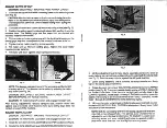
Pocket Cutter base and align
the LEFT
side
of the material (see Fig. 8) with
the
LEFT
rib
index
(correspondingto
materialwidth).
Seatmaterialagainstthe
drill guide
bushing.
4.
Rotate
the
work
clamp
lever counterclockwise to
clamp the material.
5. Positionthe
RIGHT
fence
against
the
workpiece
and
t i g h t e n
the
two
fence
clamp
knobs.
,
6.
Loosen
the
work clamp and
move
the
scrap material to
align its
RIGHT
edge with
the RIGHT
rib
index
(see
Fig. 9).
7. Tighten work clamp. Move
LEFT
fence
against
scrap materialandtighten
fence
clamp knobs.
8.
Lift
up on
the
motor
unit
and
hold
while
turning
transport
lock knob
counterclockwise
FOUR
TO
SIX
FULL
TURNS
to
release
lock. Slowly lower
motor and check for
free movement.
POSITION TO
INDEX RIBS
The
index
ribs
are primarily
used for
material that
is 3" to
10"
in
width.
1. CAUTION:DISCONNECTPOCKETCUTTERFROMPOWERSOURCE,
tilt
motor to the UP position and engage transport lock.
2.
Remove fences from
Cutter.
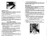
3. To position workpiece
for
RIGHT cut, place the workpiece into machine
(see
Fig. 10) so that
its RIGHT edge aligns with
the RIGHT index rib
(corresponding with the material width). Rotate work clamp lever counter
‑
clockwise to
secure
workpiece
to
machine.
4. Toposition workpiece for
LEFT
cut, placethe workpiece
into machineso
that its
LEFT
edge
aligns
with
the
LEFT index rib.
Rotate
work
clamp
lever
counterclockwise to
secure
workpiece
to machine.
5. Lift up on
the motor
unit and hold while turning transport lock knob
counterclockwise FOUR TO SIX FULLTURNS to release
lock. Slowly lower
motor
and check for free
movement.


