

6 - ENG
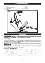
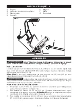
COMPONENTS (FIG. 1)
A . Handle
B . Rubber cap (plunger)
C . Guide plate
D . Pusher
E . Magazine
F . Mallet
G . Air Inlet
A
B
C
F
D
E
G
FIG. 1
\
ASSEMBLY
Disconnect air line from tool and remove fasteners from magazine
before making adjustments or personal injury may result.
AIR FITTING
The tool is equipped with a 1/4" (6 .4 mm) male quick connector coupling . A 3/8" (9 .5 mm)
male quick connector coupling is available from PORTER-CABLE and may be used when a
1/4" (6 .4 mm) supply line is not available .
NOTE:
A 3/8" (9 .5 mm) supply line (and fittings) are required for maximum tool performance .
Always use couplings that relieve all pressure from the tool when it is
disconnected from the power supply . Always use hose connectors that shut off air supply
from compressor when the tool is disconnected .
TO INSTALL AN AIR FITTING
1 . Wrap the male end of the fitting with thread seal tape prior to assembly to eliminate air
leaks .
2 . To install a 1/4" (6 .4 mm) fitting: screw it directly into the air inlet and tighten firmly .
NOTE:
If an adapter is in the air inlet, remove it prior to inserting the fitting .
3 . To install a 3/8" (9 .5 mm) fitting: screw the fitting into the 3/8" (9 .5 mm) adapter and then
into the air inlet of the tool and tighten firmly .


