background image

13

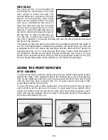
GUIDE SCREWS 

For most applications, position the 
buttonhead guide screws (A) Fig. 11 
so that a straight-edge (B) placed on 
them will just barely clear the pad edge 
(C). In this position, the pad rim will 
not rub the clapboard edge on which 
the screws ride. You can adjust the 
screws to keep the pad edge farther 
away from the overlapping clapboard. 
To change the positions of the screws, 
loosen the lock nuts, adjust the screws 
and tighten lock nuts. Make sure the 
screws do not turn or change position 
while tightening lock nuts.

VARIABLE SPEED 

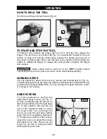
You can adjust the speed of this tool by turning the thumbwheel (C) Fig. 10. 
Thumbwheel position #1 provides the slowest operating speed (3300 RPM) and 
position #6 the fastest (4500 RPM). You can change the speed while the  motor 
is running or not running.

HOW TO HOLD THE TOOL

Hold the tool firmly with both hands (Fig. 9).

TO START AND STOP THE TOOL

To start the tool, depress the trigger (A) Fig. 10. To stop the tool, release the 
trigger. This tool has a lock button (B) Fig. 10, conveniently located in the tool 
handle. To keep tool running continuously, depress the trigger (A) and push in 
the switch locking button (B) on the left side of the handle. While holding the 
button in, release the trigger. To release the locking button, depress the trigger 
and release.

Make certain that the switch is in the “OFF” position before 

connecting the tool to the power source to avoid unintentional starting.

Fig. 9

Fig. 10

Fig. 11

OPERATION

B

A

C

B

C

A

Содержание 7403

Страница 1: ..._______________________ Serial No ______________________________________ IMPORTANT Please make certain that the person who is to use this equipment carefully reads and understands these instructions before starting operations ESPAÑOL PÁGINA 19 FRANÇAIS PAGE 35 To learn more about Porter Cable visit our website at http www porter cable com Copyright 2005 Porter Cable Part No A14107 09 10 05 Rev A M...

Страница 2: ...cal Service Manager Porter Cable 4825 Highway 45 North Jackson TN 38305 Information regarding the safe and proper operation of this tool is available from the following sources Power Tool Institute 1300 Sumner Avenue Cleveland OH 44115 2851 www powertoolinstitute org National Safety Council 1121 Spring Lake Drive Itasca IL 60143 3201 American National Standards Institute 25 West 43rd Street 4 floo...

Страница 3: ... wear NIOSH OSHA approved properly fitting face mask or respirator when using such tools CALIFORNIA PROPOSITION 65 It is important for you to read and understand this manual The information it contains relates to protecting YOUR SAFETY and PREVENTING PROBLEMS The symbols below are used to help you recognize this information SAFETY GUIDELINES DEFINITIONS indicates an imminently hazardous situation ...

Страница 4: ...tions Water entering a power tool will increase the risk of electric shock d Do not abuse the cord Never use the cord for carrying pulling or unplugging the power tool Keep cord away from heat oil sharp edges or moving parts Damaged or entangled cords increase the risk of electric shock e When operating a power tool outdoors use an extension cord suitable for outdoor use Use of a cord suitable for...

Страница 5: ...stments changing accessories or storing power tools Such preventive safety measures reduce the risk of starting the power tool accidentally d Store idle power tools out of the reach of children and do not allow persons unfamiliar with the power tool or these instructions to operate the power tool Power tools are dangerous in the hands of untrained users e Maintain power tools Check for misalignmen...

Страница 6: ...7 Do not use the spindle lock pin to stop the spindle from rotating 8 Do not sand lead based paint Lead based paint should only be removed by a professional 9 Wear eye and hearing protection Always use safety glasses Everyday eyeglasses are NOT safety glasses USE CERTIFIED SAFETY EQUIPMENT Eye protection equipment should comply with ANSI Z87 1 standards Hearing equipment should comply with ANSI S3...

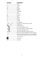
Страница 7: ...ns per minute or d c direct current or a c alternating current 2 two phase alternating current 2N two phase alternating current with neutral 3 three phase alternating current 3N three phase alternating current with neutral rated current of the appropriate fuse link in amperes time lag miniature fuse link where X is the symbol for the time current characteristic as given in IEC 60127 protective ear...

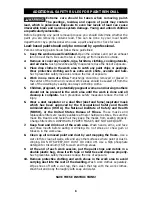
Страница 8: ... Children pregnant or potentially pregnant women and nursing mothers should not be present in the work area until the work is done and all cleanup is complete Such preventive safety measures reduce the risk of injury 6 Wear a dust respirator or a dual filter dust and fume respirator mask which has been approved by the Occupational Safety and Health Administration OSHA the National Institute of Saf...

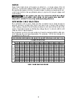
Страница 9: ...te on the tool Several models however are designed for A C current only Refer to the specification plate on your tool for proper voltage and current rating Do not operate your tool on a current on which the voltage is not within correct limits Do not operate tools rated A C only on D C current To do so may seriously damage the tool SAVE THESE INSTRUCTIONS RECOMMENDED EXTENSION CORD SIZES FOR USE W...

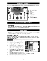
Страница 10: ... and seat the hex spacer into the hex socket of the handle boss 4 Place the other washer B Fig 2 on the bolt and secure it with a hex nut E Tighten securely 5 Thread the auxiliary handle into the collar DISCONNECT TOOL FROM POWER SOURCE A Left Handle Boss B Bolt C Hex Spacer D Collar E Washer 2 F Hex Nut G Right Handle Boss Fig 1 A Fig 2 AUXILIARY HANDLE An auxiliary handle to be mounted on either...

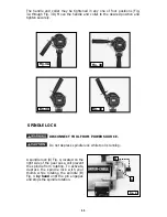
Страница 11: ...the spindle B Fig 4 by hand until the pin engages and stops the spindle rotation DISCONNECT TOOL FROM POWER SOURCE SPINDLE LOCK Do not depress spindle lock while tool is running Fig 4 Fig 3A Fig 3B Fig 3C Fig 3D The handle and collar may be tightened in any one of four positions Fig 3A through Fig 3D Move the handle and collar to the desired position and tighten securely B A ...

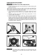
Страница 12: ...en the screws firmly 3 Thread the aluminum and sponge rubber back up pad A Fig 7 on the machine spindle Hand tighten 4 Select the Porter Cable tungsten carbide disc with grit size best suited for the job Center the disc on the back up pad Fig 8 and thread the disc retaining nut on the spindle Depress the spindle lock pin A Fig 8 and rotate pad by hand until the lock engages and stops the pad rotat...

Страница 13: ...osition 1 provides the slowest operating speed 3300 RPM and position 6 the fastest 4500 RPM You can change the speed while the motor is running or not running HOW TO HOLD THE TOOL Hold the tool firmly with both hands Fig 9 TO START AND STOP THE TOOL To start the tool depress the trigger A Fig 10 To stop the tool release the trigger This tool has a lock button B Fig 10 conveniently located in the t...

Страница 14: ...32 below the pad edge see Fig 12 For removing very thin coats of paint make the depth of cut smaller by moving the rail above the pad downward Use a piece of scrap lumber to try several positions until you find the height best suited for the job Do not change the position of the rail that is 1 32 below the pad edge USING THE PAINT REMOVER SPOT SANDING To sand small areas start the motor and place ...

Страница 15: ...areas left to right right to left up down or in a circular path until you have covered the entire surface SANDING UP TO WINDOW OR DOOR FRAMES If the window or door frame is on your left adjust the left rail of the paint remover so that it is higher than the edge of the pad Adjust the right rail so that it is lower than the edge of the pad If the window or door frame is to your right adjust the rai...

Страница 16: ...operating conditions No further lubrication is necessary BRUSH INSPECTION If applicable For your continued safety and electrical protection brush inspection and replacement on this tool should ONLY be performed by an AUTHORIZED PORTER CABLE SERVICE STATION or a PORTER CABLE DELTA FACTORY SERVICE CENTER At approximately 100 hours of use take or send your tool to your nearest authorized Porter Cable...

Страница 17: ... also order parts from your nearest factory owned branch or by calling our Customer Care Center at 1 888 848 5175 to receive personalized support from highly trained technicians SERVICE AND REPAIRS All quality tools will eventually require servicing and or replacement of parts For information about Porter Cable its factory owned branches or an Authorized Warranty Service Center visit our website a...

Страница 18: ...rized Service Stations ANY IMPLIED WARRANTY INCLUDING THE IMPLIED WARRANTIES OF MERCHANTABILITY AND FITNESS FOR A PARTICULAR PURPOSE WILL LAST ONLY FOR ONE 1 YEAR FROM THE DATE OF PURCHASE To obtain information on warranty performance please write to PORTER CABLE 4825 Highway 45 North Jackson Tennessee 38305 Attention Product Service THE FOREGOING OBLIGATION IS PORTER CABLE S SOLE LIABILITY UNDER ...

Страница 19: ...UICKSET II QUICKSET PLUS RIPTIDE design SAFE GUARD II SAFE LOC Sanding Center SANDTRAP design SAW BOSS Sawbuck Sidekick SPEED BLOC SPEEDMATIC SPEEDTRONIC STAIR EASE The American Woodshop design The Lumber Company design THE PROFESSIONAL EDGE THE PROFESSIONAL SELECT THIN LINE TIGER TIGER CUB TIGER SAW TORQBUSTER TORQ BUSTER TRU MATCH TWIN LITE UNIGUARD Unifence UNIFEEDER Unihead Uniplane Unirip Uni...

Отзывы: