background image

T r a n s m i s s i o n  

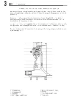
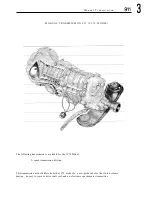
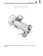
T Y P E   9 2 5   S P O R T O M A T I C   T R A N S M I S S I O N   ( 1 9 7 4   M O D E L )  

Beginning  with 

Type 911 and 911 S vehicles  can  optionally  b e  equipped with t h e  Type 

transmission. 

This 

differs  from that used  in 1973 models only 

in 

the aspect  of  changed  torque 

converter  ratio (see Technical Data,  page 

Содержание 1972 911

Страница 1: ...Workshop manual DR ING h c F PORSCHE KG STUTTGART ZUFFENHAUSEN ...

Страница 2: ... I and 11 S u r v e y o f t h e i n d i v i d u a l A s s e m b l y G r o u p s Engine and Clutch Fuel System Transmission Front Axle Rear Axle Brakes Wheels Tires Code No 1 Code No 2 Code No 3 Code No 4 Code No 5 Code No 6 Pedal Controls and Manual Controls Code No 7 Maintenance Jobs Technical Data Code No 0 Body Code No 8 Electrical System Code No 9 For identification of the volumes the back of ...

Страница 3: ...Motor und Kupplung Engine and Clutch Moteur et Accouplement Motore e Frizione ...

Страница 4: ...haust gas recirculation system Engine cross section with emission control 1978 1979 models Emission control layout 1980 model 0 2 T e c h n i c a l d a t a General data Power performance curves Technical data Type 911 T Continuous Injection System CIS Technical data Type 911 S Carrera 1974 model Full power performance 1974 model Technical data Type 911 S and Carrera 1975 model Engine tightening da...

Страница 5: ...ving and installing Auxiliary pressure relief valve disassembling and assembling Oil cooler coil removing and installing Oil cooler removing and installing 3 2 Oil tank removing and installing 1974 model 3 3 Pressure relief valve cooling coil removing and installing 1974 model 3 4 Pressure relief valve disassembling and assembling 1974 model 3 5 Oil cooler coil removing and installing 1974 model C...

Страница 6: ... 911 SC 1978 model Piston weight classes 911 SC from 1981 models 7 CRANKCASE AND CRANKSHAFT 7 1 C r a n k c a s e a n d c r a n k s h a f t Crankcase measuring and reconditioning Modified flywheel installation 1978 model Flywheel with pilot bearing 1980 model Oil filter screen and suction plate removing installing C r a n k s h a f t Crankshaft changes 1972 model Crankshaft dimensions Connecting r...

Страница 7: ......

Страница 8: ... s c r i p t i o n 911 1 ENGINE CHANGES B E G I N N I N G WITH 1 9 7 2 MODELS G e n e r a l I n f o r m a t i o n Beginning with 1972 models Type 911 engines have a cubic displacement of 2 4 liters 2341 c 142 8 cu in ...

Страница 9: ...ribed on the pages that follow Summary of Changes 1 Technical Data 2 Crankcase 3 Crankshaft 4 Connecting rods and bearings 5 Pistons 6 Location of oil tank and oil lines 7 Clutch pressure plate throwout bearing and clutch disc 8 Ignition see Group 9 Electrical System 9 Fuel system see Group 2 ...

Страница 10: ...ousing in front of the rear axle The oil filler neck is now accessible from the outside It is located under a hinged lid in the right rear fender The oil filter housing is separated from the tank and mounted on the right engine compartment wall The auxiliary oil cooler under the right front fender continues to be standard equipment in Type 911s vehicles ...

Страница 11: ...nler engine mounted 7 3 Oil pump a Pressure pump 8 b Scavenging pump 9 4 Oil tank 5 Housing with thermostat 10 opens to auxiliary oil 1 1 cooler at 8 3 1 8 2 0 Full flow oil filter Crankcase breather to oil tank Oil screen Engine thermostat opens to oil cooler at 83Oc 182 Air cleaner Oil tank breather to air cleaner ...

Страница 12: ...OIL COOLER S C H E M A T I C T Y P E 9 1 1 s VEHICLES FROM 1 9 7 3 M O D E L ON 1 Oil tank 2 Pressure relief valve 3 Inlet pipe 4 Return pipe 5 Radiator coil ...

Страница 13: ......

Страница 14: ......

Страница 15: ... O i l screen in crankcase Connecting rod Piston Cylinder Exhaust valve Valve guide Oil hose connector oil tank to oil pump Valve spring Rocker arm shaft Camshaft Rocker arm Intake valve Fuel injector Upper air shroud Throttle valve housing Fuel injection line Cold start enrichment nozzle Crankcase ventilation filter Air filter housing retaining clips ...

Страница 16: ...D e s c r i p t i o n 9 1 1 1 ...

Страница 17: ... Crankcase Oil pump Pressure side to lubrication points Suction side to oil tank Connecting shaft Oil screen O i l drain plug magnetic Crankshaft Connecting rod Sprocket gear Intermediate shaft Heat exchanger Exhaust muffler Distributor drive gear Belt pulley V belt AC generator Upper air shroud ...

Страница 18: ... g s g a p i n m m T h r o t t l e v a l v e h o u s i n g Cylinder base bore in crankcase increased from 92 mm dia to 97 mm dia 90 mm dia instead 84 mm dia Piston pin offset by 0 4 mm instead 0 8 mm Cylinder walls coated with NIKASIL compound Cooling fins reduced from 15 to 11 Advance curve changed TDC at 850 950 rpm BOSCH W 265 P 21 0 55 BOSCH W 260 T 2 0 1 BERU 265 14 3P 0 55 BERU 260 14 3 0 7 ...

Страница 19: ...e 2 Pistons Piston heads in Type 911 S engines are marked A 2 Rype 911 pistons by comparison have a deeper depression and a higher protrusion without special markings 3 Cylinder head The mounting orifice for the injection valve is discontinued since the valve is relocated to the intake stack 4 Type 911 and 911 S engines received modified camshafts with changed valve timing ...

Страница 20: ......

Страница 21: ...D e s c r i p t i o n ...

Страница 22: ...D e s c r i p t i o n 911 1 ...

Страница 23: ...l injector 3 Thermo time switch 4 Oil temperature switch 5 Intake housing 6 Cold start valve 7 Vacuum control 8 Ignition distributor 9 Auxiliary air valve 10 Throttle valve switch 1 1 Throttle housing 12 Sensor plate 1 3 Mixture control unit 14 3 way catalytic converter 15 Muffler 16 Fuel injection line ...

Страница 24: ... Maximum torque DIN SAE engine speed 84 mm 3 31 in 70 4 mm 2 77 in 2341cc 1 4 2 8 in 7 5 1 140 137 20 mkp 166 ft lb 4000 rpm four stroke gasoline engine with two opposing cylinder banks 6 horizontal three cylinders per bank 8 4 m m 3 31in 70 4 mm 2 77 in 2341cc 142 8 1 in 8 0 1 165 157 21 mkp 174 ft lb 4500 rpm 84 mm 3 31 in 70 4 mm 2 77 in 2341cc 1 4 2 8 in 8 5 1 190 181 22 mkp 181 ft lb 5200 rpm...

Страница 25: ...9 1 1 T e c h n i c a l D a t a ...

Страница 26: ...earing one piece bushing hard lead lined dry sump oil cooler on crankcase in fan air stream full flow two piece pressure casting of alurninum magnesium alloy forged surface hardened two plain journal eight plain journal split inserts 3 layer thrust bearing one piece bushing hard lead lined dry sump oil cooler on crankcase in fan air stream auxiliary cooler in front of vehicle full flow two piece p...

Страница 27: ...ze forged steel split inserts 3 layer bronze pressed in light alloy die cast floating with circlips two compression rings one oil scraper individual grey cast iron sleeve with finned light alloy jacket light alloy finned individual castings for each cylinder shrunk in grey cast iron shmnk in special bronze forged steel surface hardened Tenifer split inserts 3 layer bronze pressed in light alloy fo...

Страница 28: ...and rocker arm M 14 x 1 25 machined into cylinder heads 1 intake 1 exhaust valve per cylinder overhead in V sodium cooled with reinforced seat 2 coil springs per valve OHC 1 camshaft per cylinder bank cast steel in three plain bearings in base metal of camshaft housing by chain 0 10 mm 0 004 in measured between valve stem and rocker arm M 14 x 1 25 machined into cylinder heads 1 intake 1 exhaust v...

Страница 29: ... 4 2 8 m m capacitive discharge system CDS 1 6 2 4 3 5 BOSCH MARELLI 50 10 974 1 BOSCH JFUDR6 0231169003 centrifugal and vacuum 5 ATC 900 rpm BOSCH 38 3 MARELLI 40 f 3 16 BTC 3 0 ATC 42 BTC 4 BTC capacitive discharge system CDS BOSCH MARELLI 50 10 974 2 BOSCH JFUDRG 0231169004 centrifugal and vacuum 5 ATC 900 rpm BOSCH 38 3 MARELLI 40 2 3 38 BTC 50 ATC 40 BTC 20 ATC capacitive discharge system CDS...

Страница 30: ...Horsepower Output Ne DIN HP b ...

Страница 31: ...911 T e c h n i c a l D a t a Full power Performan s C1L Engine Speed n rpm vJ ...

Страница 32: ...Full power Performance Type 911S 180 160 150 140 E I130 z 6 V 120 Q z 110 3 Q CI 6100 L Q 3 90 0 e a 2 80 0 I 70 60 50 Md max 22 mkp at 5200 rpm I I I Engine Speed n rmp ...

Страница 33: ...T e c h n i c a l D a t a 911 1 Full power Performance Carrera Q Engine Speed n rpm a ...

Страница 34: ...bs C y I i n d e r s a n d P i s t o n s Cylinder material Piston material I g n i t i o n Ignition distributor Breaker point gap Dwell angle Basic ignition adjustment Spark plugs gap in mm F u e l i n j e c t i o n p u m p 6 90 70 4 2687 2653 8 5 1 210 154 6300 26 255 5100 78 57 91 lo a approx 182 402 Light alloy with NIKASIL coated cjlinder bore Forged aluminum alloy BOSCH Nr 023 116 9011 MARELL...

Страница 35: ...n kg or lb V a l v e T i m i n g Camshaft left part number Camshaft right part number Camshaft identification left Camshaft identification right Cam height and base circle radius intake Cam height and base circle radius exhaust Intake valve lift at TDC overlap with 1 mm valve clearance intake valve exhaust valve Valve timing with 1 mm valve clearance in degfees of crankshaft rotation exhaust opens...

Страница 36: ...911 T e c h n i c a l D a t a Full power Performance Ne max 140 PS DIN1 at 5700 rpm 40 Md max 20 5 mkp at 4000 rpm 30 I 2000 3000 4000 5000 6000 7000 80 peed n rprn ...

Страница 37: ...oke mm inch Displacement actual cc CID Compression ratio Horsepower r a t i n g max according to DIN 70020 HPIKW according to SAE J 245 net HPIKW all at crankshaft rpm of four stroke gasoline engine with two opposing cylinder banks 6 horizontal 3 cylinders per bank 90 3 54 70 4 2 77 2687 163 97 6 horizontal 3 cylinders per bank 90 3 54 70 4 2 77 2687 163 97 ...

Страница 38: ...ts RON Fuel consumption UFG under mixed traffic conditions approx Engine weight kg lbs approx Valve timing with1 mm valve clearance Intake opens Intake closes Exhaust opens Exhaust closes Intake valve stroke at TDC overlap with 0 1 mm valve clearance model 75 24 235 168 228 3800 55 8 41 53 2 39 8 91 12 14 182 402 lo ATC 35 ABC 29 BBC 7 BTC 0 7 0 9 0 5 0 7 24 235 168 228 4000 65 48 62 2 46 5 91 13 ...

Страница 39: ...c i a a 911 1 ...

Страница 40: ...fl T e c h n i c a l D a t a ...

Страница 41: ...ine Speed n rpml W V ...

Страница 42: ...take closes Exhaust opens Exhaust closes Intake valve lift at overlap TDC with 0 1 mm valve clearance in mm Valve lift at 0 1 mm clearance Intake valve in mm Exhaust valve in mm Camshaft right Camshaft left Identification on face of camshafts Camshaft right Camshaft left Valve spring sizes Intake valve in mm Exhaust valve in mm E x h a u s t b e a t i n g USA 6 after TDC 50 after BDC 24 before BDC...

Страница 43: ...out air conditioner Double belt pulley to crankshaft with air conditioner Safety valve plug to crankcase Pressure relief valve plug to crankcase Adapter oil pressure sender to crankcase Adapter in crankcase oil return line Cylinder head nuts Rocker arm shafts Nut on camshaft Hex head bolt on camshaft Cover to camshaft housing Adapter to cylinder head air injection Air line coupling nut to adapter ...

Страница 44: ...T e c h n i c a l D a t a 911 1 ...

Страница 45: ...ax engine speed Cutoff speed of speed limiter in distributor Engine weight dry Valve Drive Valve clearance cold engine measured betw valve and adjusting screw Intake Exhaust Valve timing at 1 mm clearance 6O o 500 ABDC 2 BBDC 2 BTDC Intake opens Intake closes Exhaust opens Exhaust c loses Intake valve lift at TDC overlap with 0 I mm valve clearance Identifying number on cam end face Camshaft left ...

Страница 46: ...gs gap 0 55mm O O22 in C o o l i n g F a n D r i v e Crankshaft fan ratio Air delivery rate L u b r i c a t i o n Oil pressure at 5000 rpm and 80 1 7 6 O Oil consumption approx approx 5 ATDC at 900 50 rpm Bosch W 235 P 21 Beru 235 14 3P 1 1 8 ltr sec 1265 at crank shaft speed of 6000 rpm 5 atm 73 5 psi ltr 600 mi 1 5 2 0 ...

Страница 47: ...ine speed Cutoff speed of speed limiter in distributor Engine weight dry Valve drive Valve clearance on cold engine measured betw valve and adjus ting screw Intake Exhaust Valve timing with 1 mm valve clearance Intake opens Intake closes Exhaust opens Exhaust closes Intake valve lift at TDC with 0 l mm valve clearance mm inch mm inch 3 3 cm inch kW HP rpm Nm lbft rpm kW HP rpm rpm kg lbs mm mm 6 A...

Страница 48: ...ia Version vaccuum hose connected Spark plugs Electrode gap C o o l i n g F a n D r i v e Crankshaftjfan ratio Air delivery rate E n g i n e L u b r i c a t i o n Oil pressure at 5000 rpm and 80 176OF Oil consumption per 600 miles mm mm mm ltr approx approx 0 Z1 mark at 950 50 rpm 15 ATDC at 1000 50 rpm Bosch W 225 T 30 0 7 Beru 225 14 3A 0 7 osch W 235 P 21 0 6 Beru 235 14 3P 0 55 1 1 8 1265 sec ...

Страница 49: ...eed Cut off speed overrev protection Engine weight dry Valve drive Valve clearance cold engine measured between valve and rocker arm adjusting screw Intake Exhaust Valve timing with1 mm valve clearance Intake opens Intake closes Exhaust opens Exhaust closes Intake valve lift at TDC overlap with 0 1 mm valve clearance mm mm USA 930 04 California 930 06 Speed limited by cutting off fuel pump 6700 to...

Страница 50: ...F a n d r i v e Crankshaft fan ratio Air delivery rate E n g i n e l u b r i c a t i o n Oil pressure at 5000 rpm and oil temp of 80 C 176 F Oil consumption approx CDI breakerless 5 BTDC at idle of 900 to 1000 rpm 0 oilotemp 80 C 176 F Bosch W 145 T 30 0 8 0 032in Beru 145 14 3 0 8 0 032 inc 930 04 air pump and catalytic converter 930 05 930 15 and 930 06 air pump catalytic converter and EGR 1 1 8...

Страница 51: ... speed limiter Engine weight dry approx Valve train mm inch mm inch 3 3 c m inch kW HP kW HP rpm Nm kpm Nm ft Ibs rPm kW 1 HP l kW 1 HP l rpm Pm kg lbs Valve clearance cold engine measured between valve and rocker arm adjusting screw Intake mm Exhaust mm Valve timing with 1 mm valve clearance Intake opens before TDC Intake closes after BDC Exhaust opens before BDC Exhaust closes before TDC Intake ...

Страница 52: ... i v e Crankshaft fan ratio Air delivery rate approx four CDI breakerless 5 BTDC at 900 to 1000 rpm idle speed vacuum hose dis 0 connected 90 C 195 F oil temperature Bosch W 5 D W 225 T 30 0 7 Beru 14 5 D 225 14 3 A 0 7 Oxygen sensor and 3 way catalytic converrer 1 1 68 1500 l sec at 6000 rpm crankshaft speed E n g i n e l u b r i c a t i o n Oil ressure at 5000 rpm and 90 C 8 195 F oil temperatur...

Страница 53: ...245 Max engine speed Cut off speed engine speed limiter Engine weight dry Valve train Valve clearance cold engine measured between valve and rocker arm Intake Exhaust Valve timing with 1 mm valve clearance Intake opens Intake closes Exhaust opens Exhaust closes Intake valve lift at TDC overlap with mm inch mm inch 3 3 cm inch kW HP kW HP rPm Nm kpm Nm ft lbs rpm k w h HPA kWA HP I rPm rpm kp lbs m...

Страница 54: ...ctrode gap mm E m i s s i o n c o n t r o l C o o l i n g b l o w e r d r i v e Crankshaft fan ratio Air delivery rate E n g i n e l u b r i c a t i o n Oil pressure at 5000 rpm and approx 90 195OF oil temperature bar psi Oil consumption ltr lo00 km 1 US qt 600 mi four CDI breakerless 5 before TDC at 950 rpm Bosch W 5 D W 225 T 30 0 7 Beru 14 5 D 225 14 3 A 0 7 Oxygen sensor with 3 way catalytic c...

Страница 55: ... may be used for these engines When installing the new belt for the first time it must be much tighter Than was formerly the case Adjusting instructions for engine prior to 1980 models with small fan Check tightness by applying thumb pressure at point midway between both pulleys Deflection approx 10 to 1 5 mm Approximate rule Tighten belt as in the past belt deflects by 10 to 1 5 mm at point midwa...

Страница 56: ...C o o l i n g S y s t e m Exhaust System E m i s s i o n C o n t r o l 9 4 3 11 0 Z W ffi ...

Страница 57: ......

Страница 58: ...er hose left Clamp adapter Adapter Screw Clamp Blower Sheet metal screw Washer Bolt Washer Heater air adapter Hose clamp Heater hose right Bolt Lock washer Washer Clamp Nut self locking Bolt Gasket Fillister head screw Clamp Notes Removal Installation Hose must not touch anything Install correctly Replace if necessary Replace Remarks ...

Страница 59: ...rimary muffler Gasket Gasket Nut Bolt Clamp Flange Seal Support disc Nut self locking Bolt Adapter Gasket Hose clamp Flex hose Screw Washer Clamp Adapter Heat exchanger Cable strap Notes Removal Installation Check for leaks and damage Replace if necessary Replace Replace Replace Replace if necessary Replace Check for damage Remarks ...

Страница 60: ... S y s t e m E x h a u s t S y s t e m E m i s s i o n C o n t r o l 911 1 EXHAUST S Y S T E M 1 9 7 8 MODELS E n g i n e T y p e 9 3 0 0 4 0 6 1 Heat exchanger 2 Exhaust pipe 3 Catalytic converter 4 Exhaust muffler ...

Страница 61: ...C o o l i n g S y s t e m Exhaust S y s t e m Emission C o n t r o l 911 1 REMOVING AND INSTALLING AIR INJECTION ...

Страница 62: ...r Plain washer Bolt Washer Plain washer Rubber bushing Spacer Air pump Winged nut Filter cover Filter cartridge Filter housing Notes Removal Installation Replace if necessary Check tension Replace if necessary Check replacing if necessary Check replacing if necessary Replace if necessary Replace if necessary Install correctly lubricate lightly Replace if necessary Remarks Refer to page 2 3 f 4 ...

Страница 63: ... s t S y s t e m E m i s s i o n C o n t r o l 911 1 Description Nut Lock washer Pulley Flat key Carrier air pump Seal Check valve Seal Air line Jet Seal Pulley engine Notes Removal Installation Replace Torque 1 0 1 2 mkp Replace Remarks ...

Страница 64: ...l TENSIONING AIR PUMP BELT A d j u s t i n g 1 Loosen bolt 2 Move air pump to left 3 Tighten bolt 4 The belt tension is correct if the belt can be pressed together about 15 mm 5 8 in at its centerpoint with considerable thumb pressure Removing installing pulley California version ...

Страница 65: ...C o o l i n g e x h a u s t a n d e m i s s i o n c o n t r o l s y s t e m s 1 R E M O V I N G A N D I N S T A L L I N G R E A C T O R S A N D EGR E Q U I P M E N T ...

Страница 66: ...pltd Bolt Heat exchanger Note when removing installing Replace every 30 000 miles Replace Replace if necessar Check for leaks and damage Replace Replace Replace if necessar Check for leaks and damage Replace Replace torque to 2 3 mkp Allow it to cool down Check for leaks to room temperature Remove heat ex changer and oil re turn line Replace install with blue side facing to ward cylinder head Repl...

Страница 67: ...EGR valve Gasket Note when removing installing Replace Replace torque to 2 3 mkp Allow it to cool down Check for leaks to room temperature Remove heat ex changer Replace install blue side facing to ward cylinder head Connect to top vacuum chamber Connect to bottom vacuum chamber Only detach at EGR valve Check replacing if necessary Replace install one betw holder and EGR line and the other betw va...

Страница 68: ... a u s t a n d e m i s s i o n c o n t r o l s y s t e m s 911 No Description EGR line Note when removing installing The right engine co Check passage ver must be removed cleaning if to replace EGR line necessary Remarks ...

Страница 69: ...efer to Group 9 REMOVING AND INSTALLING EGR VALVE R e m o v i n g 1 Disconnect vacuum hoses 2 Detach EGR valve outlet pipe at valve 3 Remove mounting bolts Note The replacement of gaskets requires detach ing the EGR line at the EGR filter and clamp I n s t a l l i n g 1 Replace gaskets Connect vacuum hoses as follows Stage I Upper chamber to left connection on throttle housing as seen in driving d...

Страница 70: ... e m s 911 1 CHECKING REACTOR FOR LEAKS N o t e The reactor s operation need not be checked It only needs to be checked for leaks 1 Let engine run at idle 2 Insert appropriate plug in outlet pipe of muffler and check reactors for leaks by listen ing Replace a leaky reactor ...

Страница 71: ...GR valve 2 Increase engine speed to about 4 000 rpm The outlet pipe from the EGR valve to the intake housing must now be hot too If the outlet pipe between the EGR valve and in take housing is not hot the following conditions could be causing this a EGR valve defective b EGR lines plugged c Vacuum bores in throttle valve housing plugged d Vacuum hoses plugged or leaking e EGR filter between muffle...

Страница 72: ...tester according to manufacturer s instructions N o t e The CO should be checked immediately after a test drive as long as the engine is still at operating temperature 5 Adjust CO to 1 5 2 0 70at idle speed of 900 50 rpm 6 Reconnect air injection hose to air pump 7 The CO must now drop below 1 0 70with the engine idling at 900 50 rpm If the CO is still above 1 0 70 there is a defect in the air inj...

Страница 73: ...taining clamp of return line 7 Pull tank partially out of the wheelhousing and remove oil line breather hoses and oil level gauge wires Remove tank 4 Detach return hose from oil tank 5 In Type 911 S also detach the oil hose from bottom of tank Make sure during installation that plastic caps between tank and body and retaining strap liner are correctly seated Coat oil hose connections with Molykote...

Страница 74: ...rt and longitudinal support Turn support to the side 6 Unscrew oil filter 7 Disconnect oil breather hoses from oil tank Remove oil tank retaining nuts accessible from engine compartment Remove oil tank Remove oil filter base I n s t a l l i n g Note the following during reassembly 1 Properly position rubber seal fitting between wheelhouse panel and oil tank Glue seal to the oil tank 2 Make sure th...

Страница 75: ...o i c i t 911 1 REMOVING A N D I N S T A L L I N G AUXILIARY PRESSURE RELIEF VALVE 1 Disconnect oil hoses 2 Remove pressure relief valve from oil tank Remove support bracket ...

Страница 76: ... r c u i t DISASSEMBLING A N D REASSEMBLING AUXILIARY PRESSURE RELIEF VALVE Nr 1 Spring Description 1 2 1 Relief valve plunger Plug Seal ring 5 1 Relief valve housing Note when removing installing Replace Remarks ...

Страница 77: ...il hoses Caution Counter with a second open end wrench 4 Remove oil cooler coil I n s t a l l i n g Apply counter force at the oil lines during in stallation to prevent damage Coat oil hose connectors with Molybdenum disulfide grease during installat ion 3 Remove Allen bolts and retaining screw from the right bumper bracket ...

Страница 78: ...re equipped with a two piece air shroud which simplifies the removal and installation of the oil cooler R e m o v i n g 1 Remove air filter top 2 Remove front engine shroud 4 Remove oil cooler air duct 5 Drain oil 3 Remove right engine shroud 6 Detach oil hose from oil cooler and remove upper retaining nuts ...

Страница 79: ...911 O i l C i r c u i t I n s t a l l i n g Install new sealing rings at the oil cooler NOTE When positioning the oil cooler on crankcase make sure that sealing rings are properly seated ...

Страница 80: ...v a l 1 Remove right rear wheel 2 Drain oil 3 Detach oil hoses and remove bolt from support tube of lower fender section 4 Remove screws from support tube and turn it to the side 5 Detach wires from oil level sender 6 Detach breather hoses and remove tank cover from tank 7 Unscrew oil filter ...

Страница 81: ...r c u i t 8 Open the lock plate remove nut and pull out support tube through the bottom 9 Remove oil tank retaining nuts and washers I n s t a l l a t i o n 1 Glue wheelhouse gasket to oil tank in proper position ...

Страница 82: ...I N S T A L L I N G PRESSURE RELIEF VALVE OF C O O L I N G C O I L BEGINNING W I T H 1 9 7 4 MODELS R e m o v a l 1 Drain oil from tank 2 Detach oil lines Remove retaining clamp from upper oil lines 4 Remove the valve C a u t i o n Catch spilling oil ...

Страница 83: ...N D REASSEMBLING PRESSURE RELIEF VALVE B e g i n n i n g w i t h 1 9 7 4 M o d e l s Description Plug Gasket Spring Plunger Plug Gasket Spring Plunger for pressure relief valve Valve housing Note when removing installing Replace Replace Remarks ...

Страница 84: ...sconnect oil hoses C a u t i o n Counterhold with a second open end wrench Catch spilling oil Remove retaining bolt and take cooler coil out 4 Remove attaching bracket I n s t a l l a t i o n 1 Apply counter force when connecting oil lines to prevent damage 2 Coat oil hose connectors with MOLYKOTE A during installation 3 Mount cooler coil without stress ...

Страница 85: ...n oil from oil tank 7 Place rubber guards on oil lines 3 Disconnect oil return hose from engine to oil tank 4 Remove rocker panel cover 5 Remove plugs in oil line and cooling coil mounting points on front wheelhousing Place both oil lines along rocker panel The top line must rest on fender connector plate Install spacers and mounting clips Only tighten mounting screws slightly 9 Connect pressure r...

Страница 86: ...oil temperature to be at least 83 C 182 F so that the pressure relief valve will release the flow of oil to the cooling coil 11 Place oil hoses along rear wheelhousing and connect If necessary cut threads on stud 12 Connect cooling coil to oil lines 13 Fasten cooling coil and lines to wheel housing 14 Tighten all oil line connections ...

Страница 87: ... the front wheel well area Only new version lines will be available from Parts after using up the former version oil lines Changes made necessary when installing new lines in cars with old oil lines without side turn signals are described in the following instructions Old oil lines R e m o v i n g New oil lines 1 Lift car on platform hoist Remove wheels on right side of car Spray rust removing sol...

Страница 88: ...lief valve housing Catch escaping oil 5 Disconnect oil lines on cooling coil or at oil hoses for cars with a front oil cooler Counterhold with a second open end wrench 6 Unscrew mounting bracket and clamps Remove oil lines I n s t a l l i n g 1 When installing new lines in cars without side turn signals proceed as follows with the mounting points in the wheel well Point A Is still applicabbe Point...

Страница 89: ...d metal screw at new mounting point when installing new oil lines in a car without side turn signals 2 Install hoses on oil lines for protection 3 Route both oil lines along side member trim Upper line must be on fender joint plate Install spacers and clamps Tighten mounting bolts only finger tight 6 Reconnect automatic antenna wires Check function of radio and antenna 7 Push in rocker panel cover...

Страница 90: ...harply and press on continuously Lip must fit tightly on body at top If necessary realign 9 Check system for leaks This requires that engine oil temperature be at least 83 c 181 F so that the governor can release flow to the cooling coil or front oil cooler Correct oil level ...

Страница 91: ... a second wrench as a counterhold Catch escapGg oil I n s t a l l i n g 3 Loosen outer nut on upper rubber mount When installing counterhold at the cooler connections to prevent damage Coat connections with Optimoly HT Check connections for leaks This requires that the regulator for the front oil cooler be open to have oil flowing through the cooler 0 0 engine oil temperature above 83 C 181 F ...

Страница 92: ...n pressure relief valve Spring old 70 mm long Spring new 86 mm long Spring guide Gasket Plug old without groove Plug new with groove Spring safety valve Plug new with groove I n s t a l l a t i o n N o t e Pressure Relief Valve from 1978 Safety Valve The 86 mm long spring for pressure relief valve may only be installed together with the spring guide ...

Страница 93: ...th a bottoming tap Pull out plug with an M 6 screw and spacer CAUTION Be careful not to damage sealing surface when removing plug 2 Loosen centering screws and slide injection tube out I n s t a l l i n g 1 Install injection tube making sure that locating bore for plug is positioned correctly CAUTION Separate bores must face upward toward intake valve covers Double bores not shown in illustration ...

Страница 94: ...y l i m d e r H e a d Lubricate new plug and hole coat with a double component adhesive hind install plug CAUTION Upset plug befoie installation if it does not fit tightly in housidg Plug is pressed in about 0 3 p m deeper than sealing surface ...

Страница 95: ...o u s i n g a n d C y l i n d e r H e a d 911 1 O V E R H A U L I N G C H A I N T E N S I O N E R T O O L S No 1 2 3 Description Adjusting ring Clamp Assembly lever Special Tool Remarks For chain lensioner 930 105 049 00 ...

Страница 96: ...the chain tensioner having Part No 930 105 049 00 or the repair kit having Part No 911 105 901 01 with modified parts are available from parts Only the new version chain tensioner may be re paired New Version Identification a Chamfer on upper part of housing i b Total height 78 2 0 2 mm and Porsche trade ...

Страница 97: ...C a m s h a f t H o u s i n g a n d C y l i n d e r H e a d 911 ...

Страница 98: ...Clamp Snap ring Spring retainer Spring Piston alum O ring 0 ring Snap ring Piston ntermediate piece 3 ring aall 5 mm Spring Zage Spring Spring guide Zhain tensioner housing Note When Removing Installing Replace Replace Replace Replace Replace Replace Replace Replace Replace Replace Replace Replace Special Inst uctions Clamp only with complete new par1 ...

Страница 99: ...k in the piston If so remove intermediate piece by lightly tapping piston against piece of wood 2 Push chain tensioner piston with mounted alu minum piston without O rings into chain tensioner housing Both pistons must move easily It is especially important that the chain tensioner piston moves easily in the lower piston position Remove any pressure spots on the pistons with emery cloth 3 Install ...

Страница 100: ...ool P 214 c until the tool rests on the edge of the chain tensioner Then tighten bleed screw again without delay Install spring spring retainer and snap ring I N S T R U C T I O N S FOR NSTALLATION OF CHAIN TENSIONER To prevent damage on the chain tensioner housing it is not permitted to pre load the timing chain with a screwdriver Force from the screwdriver could deform the chain ten sioner housi...

Страница 101: ... have to be removed Only grease has to be removed from the surface A new coat of sealing compound should be applied immediately after the cleaning solution has dried The new Loctite will dissolve the old compound remaining in the surface finish and become hard again after assembly Should it be necessary to remove the old sealing compound the use of a fine steel brush is recommended for this work A...

Страница 102: ... t e Make sure spring retainer has perfect fit in special tool machining special tool if necessary INSTALLED DIMENSIONS FOR 2 4 LITER ENGINE NOTE The above values can also be applied to the 2 2 liter engines in the course of repair Vehicle Type Engine Type Intake Valve Exhaust Valve 911 T 911 51 911 61 35 0 3 mm 35 0 3 mm 911 E 911 52 911 62 34 0 3 mm 34 0 3 mm 911 S 911 53 911 63 35 5 0 3 mm 34 5...

Страница 103: ...2 7 AND 3 0 LITER ENGINES Vehicle T Y P Engine Type Intake Valve Exhaust Valve N o t e The tolerances for cylinder heads of Carrera 3 0 and 911 SC models have been limited for manu facturing reasons The distance of 34 5 mm must not be exceeded the lower tolerance value would be ideal ...

Страница 104: ...ith Hexagon Head Mounting Bolts for Sprocket TOOLS No 1 2 3 4 5 Description Holding wrench for sprockets Puller 6 7 Dial gauge holder Clamp for chain tensioner Dial gauge with tip Special Tool 9191 P 212 Assembly lever Feeler gauge Remarks P 207 P 214 9182 P 213 Standard Tip length approx 40 mrn ...

Страница 105: ... B a s i c S e t t i n g 1 Turn crankshaft until mark Z 1 on pulley is aligned with joint of crankcase or stripe on fan housing 2 Position both camshafts so that punch marks face up Engine has its basic setting cylinder no 1 TDC and cylinder no 4 overlap by adjusting mark Z 1 on pulley to joint and punch marks on camshafts to face up ...

Страница 106: ...ial Tool P 9191 2 Pre load timing chains N o t e To avoid damage on chain tensioner housing it is not permitted to pre load timing chains with a screwdriver Supporting the screwdriver on the chain tensioner housing could deform the latter and cause seizure of the aluminum piston Only use Special Tool 9182 for pre loading N o t e Should one of the camshafts be turned out of basic setting position p...

Страница 107: ...e s Engine 930 16 1 4 1 7 mm Ideal value 1 55 mm 5 Unscrew and remove mounting bolt on left sprocket and pull out locating pin with Special Tool P 212 7 Install locating pin again and tighten bolt finger tight while holding 0 8 Turn crankshaft clockwise two turns 720 and re check setting Indicated vaiue should be within tolerances 9 Tighten bolt of left camshaft to final torque of 120 Nm 86 ft lb ...

Страница 108: ...GINNING WITH 1 9 7 2 MODELS 1 New pistons with flatter piston tops to reduce compression ratio 511 T 7 5 1 911 E 8 0 1 911 S 8 5 1 Required fuel octane rating 91 2 Changed piston ring 3 New table of dimensions for pistons and cylinders beginning with 1972 models ...

Страница 109: ...0 84 010 84 020 83 960 84 020 84 030 83 970 T y p e 9 1 1 E P i s t o n s 1st oversize 0 K D 1 1 K D 1 2 K D 1 2nd oversize 0 KD 2 1 KD 2 2 K D 2 Cylinder piston clearance 0 04 5 0 065 Piston weight 354 3 g Standard 0 1 2 1st oversize 0 K D 1 1 KD1 2 KD1 2nd oversize 0 K D 2 1 ICD 2 2 K D 2 Tolerances 0 005 m m 83 970 83 980 83 990 84 220 84 230 84 240 84 470 84 480 84 490 Cylinder piston clearanc...

Страница 110: ... 84 500 84 510 84 470 1 KD 2 84 510 84 520 84 480 2 KD 2 84 520 84 530 84 490 Cylinder piston clearance 0 025 0 045 Piston weight 376 2 3g Tolerances Standard S C H M I D T 0 007 0 008 0 84 000 84 010 83 970 1 84 010 84 020 83 980 2 84 020 84 030 83 990 1st oversize 0 KD 1 84 250 84 260 84 220 1 KD 1 84 260 84 270 84 230 2 K D 1 84 270 84 280 84 240 2nd oversize 0 KD 2 84 500 84 510 84 470 1 KD 2 ...

Страница 111: ... n d e r s a n d P i s t o n s C Y L I N D E R H E I G H T T O L E R A N C E GROUPS 1 9 7 2 m o d e l s 2 4 l i t e r s Cylinder Installation Height Code mark Standard Cylinder Height Reconditioned Cylinda Height ...

Страница 112: ... a r r e r a 2 7 P i s t o n s Piston diameter D 1 Standard Tolerances stamped 2 0 005 90 OOO 90 010 89 950 90 010 90 020 89 960 90 020 90 030 89 970 Cylinder piston clearance 0 025 0 045 Piston weight 392 i3 kg CYLINDER HEIGHT TOLERANCE OF 2 7 LITER ENGINES Cylinder Installation Height Code Standard Cylinder Height Oversize pistons and cylinders are not provided ...

Страница 113: ...ter D 1 Standard Tolerances stamped 0 0005 0 90 000 90 010 89 970 1 90 010 90 020 89 980 2 90 020 90 030 89 990 Cylinder piston clearance 0 025 0 045 PISTON AND CYLINDER DIMENSIONS LS V e r s i o n T y p e 9 1 1 P i s t o n s Cylinder markings Cylinder Piston bore diameter diameter Dl Permissible weight difference Standard stamped Cylinder piston clearance 0 035 0 060 in pistons of one set 6 g max...

Страница 114: ...ves In such case remove the ring compressor check the piston rings for location and repeat the procedure carefully pushing the cylinder onto the piston I n s t a l l i n g Piston Rings The piston rings can be installed in their grooves by hand and without the use of tools When installing rings1 and 2 make sure that the rings are placed in the sequence and position shown in the illustration I n s t...

Страница 115: ...dard Size stamped 0 90 000 90 012 89 960 89 972 1 90 012 90 024 89 972 89 984 2 90 024 90 036 89 984 89 996 Cylinder piston clearance 0 028 0 052 mm GAP OF LS PISTON RINGS Make Piston Ring Gap in mm Gap wear limits in mm R ring Top 0 2 0 4 1 0 MAHLE N ring Center 0 15 0 35 1 0 SCHMIDT SS 50 ring Bottom 0 4 1 4 2 0 3 piece consisting of expander and 2 rails ...

Страница 116: ...iston ring end gap clearance Rings slid in to height of cylinder base gasket P i s t o n D Measuring point for wear At height of lower edge of piston pin bore C a u t i o n Replace pistons and cylinders if clearance exceeds 0 15 mm PISTON RING END GAP Piston Ring End Gap mm new size Compression ring I and I1 0 1 0 2 Oil scraper ring I11 0 15 0 3 Oil scraper ring 111 3 piece LS ring 0 4 1 4 see che...

Страница 117: ...nder bore Piston marking diameter mm diameter D mm Standard size stamped Clearance between cylinder and piston 0 025 0 042 mm P I S T O N AND CYLINDER S I Z E S 9 1 1 SC f r o m 1 9 7 8 M o d e l K S Cylinder Cylinder bore Piston marking diameter mm diameter D mm Standard size stamped Clearance between cylinder and piston 0 023 0 044 mm ...

Страница 118: ...remain with the corres ponding pistons and should not be mixed up within an engine set Watch this when disassemb ling and assembling an engine marking parts if necessary Weight groups MAHLE Pistons Pistons weighed with attachments piston pins piston rings snap rings Engine type Standard production Max difference in weight 4 g For installation Max difference in weight 8 g I Total Piston Weight in g...

Страница 119: ... Standard production Max difference in weight 4 g For Service Sector Max difference in weight 8 g Total Piston Weight in g Weight Class Within a Set Weight Classes KS Pistons Pistons weighed with attachments piston pins piston rings snap rings Code Engine Type Standard Production Total Piston Weight in g Weight Class Within a Set Max difference in weight 4 g Code For Service Sector Max difference ...

Страница 120: ... necessary Measure all 8 main bearing bores with the inside micrometer If the bores are too tight they should be re amed with the main bearing reamer to stan dard diameter of 62 000 mm Bore diameter for main bearings 1 r 8 is 62 000 to 62 019 mm If the bores are too large they should be re amed to B bearing oversize of 62 25 mm diameter Control dimension for the B bearing is 62 25 mm to 62 269 mm ...

Страница 121: ...en in bench vise S k e t c h for S e l f M a d e T o o l T bar 40 x 80 x 7 mm All edges beveled 2 Insert end bearing bushing EL35 in bore of Bearing 8 Insert rod 35 x 1200 mm with main bearing reamer and ream Bearing P until Bearing 2 is guided reamer centers automatically in bore of Bearing 1 4 Insert end bearing bushing EL35 in bore of Bearing 1 5 Ream all bearing bores until reamer reaches end ...

Страница 122: ...C r a n k c a s e and F l y w h e e l 911 1 6 Remove end bearing bushing from bearing bore 8 and fullv ream bear in 8 ...

Страница 123: ...F l y w h e e l 9 1 1 1 M O D I F I E D FLYWHEEL I N S T A L L A T I O N 1 9 7 8 MODELS No 1 2 3 4 Description Socket head Flywheel Bushing Crankshaft Qty 9 1 1 1 Note When Removing Installing Torque 9 mkg Special Instructions ...

Страница 124: ... T f r o m 1 9 8 0 M o d e l No Description Screw M 6x12 Bushing with needle b e r i n g Bolt Flywheel Crankshaft Note When Removing Installing Tighten to specified torque lock with Loc tite 270 First secure flywheel then bushing Tighten to specified torque Special Instructions ...

Страница 125: ...5 6 7 8 Description Oil drain plug Seal Nut Washer Zover for oil filter scree 3 1 filter screen with iuction plate Note When Removing Installing Replace Tighten to about 10 Nrr 7 ft lb Check for deformation replacing if necessary Watch installed position oil drain plug must face in recess of suction plate Replace Replace Special Instructions ...

Страница 126: ...the old compound need not be removed It is only necessary to remove grease from the surface and to apply a coat of new sealing compound after the grease removing solution has dried The new Loctite will dissolve the old compound in the surface finish and harden again after assembly Should it be absolutely necessary to remove the old sealing compound a fine steel brush is recommended for this work A...

Страница 127: ... W I T H 1 9 7 2 MODELS Distributor mounting flange C H A N G E D C R A N K S H A F T B E G I N N I N G W I T H 1 9 7 2 MODELS Stroke 70 4 m m Crankpin diameter 51 990 51 911 Crankpin width 24 m m Beginning with 1972 models all crankshafts have counterweights See next page for crankshaft dimensions ...

Страница 128: ... 1 2098 mm 56 490 56 471 51 490 51 471 30 493 30 480 64 500 64 310 in 2 2240 2 2233 2 O272 2 0264 1 2005 1 2000 2 5394 2 5319 mm 56 240 56 221 51 240 51 221 30 243 30 230 in 2 2142 2 2134 2 0173 2 0166 1 1907 1 1902 Crankshaft pulley seat Thrust diameter bearing d 6 Width A 29 993 29 960 28 000 Grind crankshaft oil seal surfxs only w h s deeply scorede Grind to 2 dimensions of 29 5 mm 1 161 in and...

Страница 129: ...pin bushing dia before installation Press fit interference in rod G Inside diameter of installed piston pin bushing finished Piston pin clearance in bushing Wear limit 127 8 0 05 mm 5 03 0 002 in 26 0 0 2 mm 1 02 0 008 in 23 8 0 1 mm 0 9370 0 004 in 56 019 56 000 mm 2 2055 2 2047 in 25 021 25 000 mm 0 9851 0 9843 in 25 035 25 055 m m 0 9856 0 9864 in 0 014 0 055 mm 0 OOO6 0 0022 in 22 033 22 020 m...

Страница 130: ...bers The end number is stamped into connecting rods furnished as spare parts Weight grams 645 654 663 672 681 690 699 708 718 grams Weight group for KD more than KD connecting rod spare part number up to Identification in connecting rod Weight variation between connectirg rods in any engine may not exceed 9 g To determine weight group weigh complete connecting rod without big end inserts ...

Страница 131: ...ich are supplied as spare parts these final digits are stamped on the shank W e i g h t above g N o t e W e i g h t group f o r i n s t a l l a t i o n S e r v i c e i n s t a l l a t i o n c o n n e c t i n g r o d P a r t N o C o n n e c t i n g r o d m a r k i n g Only connecting rods which do not differ in weight by more than 9 g may be installed in one engine To determine a weight group weigh...

Страница 132: ...ed engines of Type 911 91 and 911 96 have a turbulence whirl cavity in the piston top This provision ensures a particularly thorough blending of the fuel air mixture I n s t a l l a t i o n n o t e The piston must always be installed so that the flat spot in the piston top faces upward towards the intake valve ...

Страница 133: ...911 C r a n k c a s e a n d C r a n k s h a f t ASSEMBLY I N S T R U C T I O N S FOR P I S T O N S ON 9 1 1 SC 1 9 8 1 M o d e l s Domed surface on piston must face intake valve ...

Страница 134: ...C r a n k c a s e a n d C r a n k s h a f t 911 MODIFIED CRANKSHAFT DRIVE 1 9 7 8 MODELS TOOLS No 1 Special Tool 9126 Description Installer for crankshaft seal Note ...

Страница 135: ...911 C r a n k c a s e a n d C r a n k s h a f t M O D I F I E D C R A N K S H A F T DRIVE 1 9 7 8 MODELS ...

Страница 136: ...Spacer Timing gear Woodruff key Connecting rod nut Connecting rod Connecting rod bea ring shell Connecting rod bolt Crankshaft Note When Removing Installing Check for wear Replace Lubricate Lubricate Lubricate Replace Replace Note installed position Tighten to specified torque Lubricate bearing surface Note installed positioi and weight Lubricate Check for wear Check for wear Special Instruction ...

Страница 137: ... s h a f t INSTALLATION INSTRUCTIONS FOR MODIFIED CRANKSHAFT DRIVE 1 9 7 8 MODELS C l a m p i n g C r a n k s h a f t Special Tool P 209 a must be modified for new crankshaft I n s t a l l i n g S e a l Drive in seal with Special Tool 9126 ...

Страница 138: ...ise rotating rotating distributor distributor with Porsche emblem with VW emblem I n s t a l l i n g C i r c l i p on C r a n k s h a f t Circlips are available in various thicknesses to take up axial play between distributor and drive gear The following circlips are available Part No Thickness mm Code 901 102 148 OO 2 4 0 901 102 148 01 2 3 1 901 102 148 02 2 2 2 901 102 148 03 2 1 3 Install timi...

Страница 139: ...i z e s 1 9 7 8 M o d e l s Crankcase bore All main bearing Connecting rod Main bearing jaw Oil seal journal Seat for timing Crankshaft pulley Thrust bearing dia bearings 1 8 journals d 1 bearing journals rial d 3 of crank dia d 4 gear dia d 5 seat dia d 6 width A d 2 shaft bearing 8 ...

Страница 140: ...ial runout measured at bearings 1 and 7 is 0 04 mm Tenifer treat crankshaft after grinding Magnaflux to check for cracks Do not straighten main bearing journals 3 and 5 after Tenifer treatment All other main bearing journals can be straightened by applying pressure to the bearing journal webs Undersize color codes 1st undersize 2nd undersize 3rd undersize 4th undersize Surface finish 7 Edge deburr...

Страница 141: ...ed and secured with lock rings on a shaft which is splined on both ends and located in the transmission housing The clutch lever is now pulled by the clutch cable instead of the cable housing 2 Pressure of the pressure plate MFZ 225 KL has been increased to a range of 650 720 kp 1430 1584 Ibs 3 Clutch disc splines have been changed from 24 to 20 an SAE designation ...

Страница 142: ...A D J U S T I N G C L U T C H 1 Turn self locking adjusting nut until clutch pedal free travel is 20 25 mm 0 8 1 0 in 2 When checking pull pedal in direction of arrow ...

Страница 143: ...REMOVING A N D I N S T A L L I N G T H R O W O U T BEARING ...

Страница 144: ... References Remove with snap ring Check for proper 9 1 2 3 pliers while pushing seating Groove must face the 1 9 l 2 3 snap ring Should not be washed only wiped with dry rag Grease guide tube contacting sur face with multi purpose grease with MoS2 additive Check for wear and replace if necessary Install in correct position 9 1 2 3 ...

Страница 145: ...g washer on the throwout bearing in proper position 2 Remove snap ring with snap ring pliers 2 Insert the throwout bearing into the and take the throwout bearing out diaphragm spring of the pressure plate together with the washers NOTE Throwout bearings are packed with special grease and therefore may not be washed 3 Install thrust washer with the groove facing the snap ring and install snap ring ...

Страница 146: ...C L U T C H 1975 MODELS 1 911 S and Carrera Pressure plate Pressure Spring No Part No Drive shell Part No MFZ225 KSph 714 785 kp 3027 056 000 915 116 OOl I4 ...

Страница 147: ...C L U T C H M O D I F I C A T I O N S 1 9 7 8 M O D E L S ...

Страница 148: ...n Socket head screw Lock washer Pressure plate Starter gear ring Clutch disc Circlip Thrust washer Release bearing Washer Spring washer Note When Removing Installing Replace Check Install in correct position Special Instructions ...

Страница 149: ...Kraftstoffanlage Fuel System Systeme d alimentation Sistema d alimentazione ...

Страница 150: ...neral checkout procedure Visual inspection Initial checks Pressure tests Leakage checks Injection valve checking Auxiliary air device checking CIS testing Bnd adjustment specifications 1974 75 models CIS testing and adjusting specifications 1976 77 models CIS testing and adjusting specifications 1978 79 models CIS testing and adjusting specifications 1980 model Testing and adjusting values 911 SC ...

Страница 151: ...moving and installing 2 2 1 9 Start enrichment valve removing and installing Fuel filter removing and installing Fuel pressure accumulator removing and installing 2 2 1 12 Injection valves removing and installing Plastic fuel lines replacing Fuel line system bleeding 2 2 1 17 Mixture control unit dismantling and assembling 2 2 2 1 Sensor plate removing and installing 2 2 2 4 Air flow sensor housin...

Страница 152: ...switch for acceleration enrichment of Oxygen Sensor control from 1981 models Correcting CO level setting on mixture control unit from 1981 models with shear off screw 2 5 1 8 3 ADJUSTMENT INSTRUCTIONS 3 1 A d j u s t m e n t i n s t r u c t i o n s f o r f u e l i n j e c t i o n s y s t e m Fuel injection pump adjusting with emission tester Idle adjusting Microswitch adjusting 1972 model C I S a ...

Страница 153: ... MODELS The 2 4 liter engines are equipped with changed injection pumps The changes consist of a wider contoured cam and modified centrifugal weights and springs Pump designation BOSCH number on data plate 9 1 1 T 0408 1 2 6 0 1 5 9 1 1 E 0408 1 2 6 0 1 4 9 1 1 S 0408 1 2 6 0 1 3 ...

Страница 154: ...tors special tool P 228 c The protractor on the injection pump control lever has not been changed The correlation checkout procedure remains same see page SF 22 The intake velocity stacks are made of plastic They form a single unit together with the lower air assembly COLD START ENRICHMENT SYSTEM CHANGES Fuel for cold start enrichment now is fed directly into each individual velocity stack The dis...

Страница 155: ...D e s c r i p t i o n ...

Страница 156: ...uel injection engines are equipped with an induction air preheating system Induction air preheating provides even induction air temperatures in lower engine speed ranges resulting in improved performance as well as lower exhaust emission values 1 F r e s h a i r f l a p 2 Hot a i r f l a p 3 T h e r m o s t a t A Hot a i r B Fresh a i r ...

Страница 157: ...ree 6 mm bolts It contains two flaps and a thermostat On of the flaps the fresh air flap is controlled by the throttle linkage The other flap hot air flap is controlled by the thermostat 2 A h os e which fetds heated air from the left heat exchange 3 A c a rn on the left throttle valve lever which controls the fresh air flap 1 Control box 2 Hot air supply duct 3 Control lever ...

Страница 158: ...flap open engine draws hot air from heat exchanger E n g i n e c o l d b e l o w 4 5 0 C 1 1 2 t h r o t t l e i n p a r t i a l l o a d p o s i t i o n Hot air flap open It opens according to position of cam Fresh outside air is added Fresh air flap is fully open in full throttle position A i r t e m p e r a t u r e r i s e s t o 4 5 5 0 C 112OF 122OF Thermostat begins to close hot air flap at 45...

Страница 159: ...pe 911 T vehicles are equipped with the continuous injection system CIS The working principle of this system depends on measuring the intake air flow rate to determine the amount of fuel to be injected The fuel distributor determines the quantity of fuel to be delivered depending on air flow rate and engine loading conditions ...

Страница 160: ...ressure regulator warm running compensa tion Heat exchanger Crankshaft Oil pump Oil screen Connecting rod Piston Cylinder Exhaust valve Valve guide Oil hose connection oil tank oil pump Valve spring Rocker arm shaft Camshaft Rocker arm Intake valve Injection valve Intake pipe Intake housing Air sensor plate Mixture control unit ...

Страница 161: ...ch act as metering ports They can be progressively opened by the control plunger The metering ports open depending on the position of the sensor plate whose moyement is transmitted to the control plunger through a lever Intake air which passes through the air flow sensor exerts a pneumatic force F l on the sensor plate 1 Venturi 2 Sensor plate 3 Lever 4 Control plunger 5 Slotted metering cylinder ...

Страница 162: ...utor is provided with a pressure regu1at ing valve which keeps the pressure drop at the metering port constant pressure difference pressure ahead of the metering port less pressure after the metering port independent of the fuel transfer rate primary system fuel pressure and injection valve opening pressure The pressure regulating valves are flat seat valves with a steel diaphragm acting as a valv...

Страница 163: ...on lines carry the fuei to the injection valves In addition a separate line carries fuel to the start enrichment valve Control pressure can be varied by two control pressure regulators one according to engine and outside temperatures the other according to accelerator pedal movement throttle actuated valve injection line start valve fuel distributor fine mesh filter Primary system fuel pressure I ...

Страница 164: ......

Страница 165: ...fuel pump Its function is to delay the initial pressure surge when the pump starts This delay is necessary to prevent the control plunger from being forced up before sufficient control pressure has been allowed to build up It also serves as a reservoir to keep the system under sufficient pressure for a short period of time when the engine is turned off F u e l F i l t e r An in 1ine filter with a ...

Страница 166: ...l a t o r Warm Running Compensation The control pressure regulator for warm running compensation contains a bimetallic spring acting on a spring loaded diaphragm During engine warm up the bimetal spring presses against the valve spring causing the control pressure to drop This results in a lower hydraulic pressure F2 greater travel of the air flow sensor plate with unchanged amount of intake air a...

Страница 167: ...hen decelerating from high rprn with throttle closed considerable vacuum builds up in the intake manifold The vacuum is channeled to an auxiliary air device As the device opens additional air bypasses the throttle creating a combustible mixture I d l e A d j u s t m e n t The adjusting method is same as that for carbure tors The idle air mass passes through the air flow sensor where it is measured...

Страница 168: ...oswitch is connected in series with it The microswitch is activated by the hand throttle lever when the latter is moved to at least 5O of the throttle valve position The thermoswitch is active up to engine temperature of approx 45 C 113 F and prevents the injection of supplemental fuel by the cold start enrichment valve when starting a hot engine V a c u u m c o n t r o l l e d w a r m u p r e g u...

Страница 169: ......

Страница 170: ...er of intake pipes at the intake housing has been changed Intake pipe for Type 911 31 mm dia 9 1 1 S 34 5mmdia 4 Mixture control unit has been calibrated for 2 7 liter engines 5 The pneumatic valve has been repositioned and also modified to the vacuum characteristics prevailing in the 2 7 liter CIS engines 6 The cold start enrichment valve has been moved to the center of the intake housing to effe...

Страница 171: ...ctivated charcoal filter with the aid of fresh air supplied by the engine cooling fan and then to the engine air filter where they mix with the induction air and are burned with it 1 Fuel tank 2 Expansion chamber 3 Activated charcoal filter 4 Cooling fan upper shroud with hose connector 5 Hose from cooling fan to activated charcoal filter 6 Hose from activated charcoal filter to engine air filter ...

Страница 172: ...or overnight The checkout should be performed at the same location where the car was parked for several hours Erroneous test results will be obtained if for instance the vehicle should be brought into a heated garage from a cold outside environment The remaining tests with the exception of the idle adjustment can be performed with the engine warm or cold The engine must be at warm operating temper...

Страница 173: ...l unit and throttle housing 2 Raise lever of air flow sensor by hand 3 Check for leaks between intake manifold and An even amount of resistance should be felt start enrichment valve O ring throughout the length of movement A quick downward movement of the lever will detach it from the sluggish control plunger at 4 Check for leaks between intake manifold and which time no resistance should be felt ...

Страница 174: ...nnection at the control pressure regulator for warm running compensation When loosening the line wrap the connection with a rag to keep fuel from spilling The upper edge of the sensor plate must now be flush with the root of the taper at a point shown in the illustration A lower positioning of up to 0 s mm is permissible If required adjustment of the flexible stop can be corrected by bending the w...

Страница 175: ...m p Minimum voltage at the connecting terminal is 11 5 volts Current draw when running is 8 5 amps maximum Check pump delivery rate Disconnect fuel return line at the connector Push a section about 50 cm long of normal fuel hose onto the connector and hold in a measuring glass Switch the ignition on for the duration of the measuring period See page 1 1 1 13 for specifications M o d i f i c a t i o...

Страница 176: ...he control pressure regu lator will have to be replaced C h e c k i n g S t a r t E n r i c h m e n t V a l v e Remove start enrichment valve see page 2 2 1 10 the fuel line remains connected Hold the start enrichment valve in a receptacle and connect to battery Bt upper fuse in rear fuse box in engine compartment left side and to ground with a piece of jumper wire Briefly switch the ignition on T...

Страница 177: ...S y s t e m C h e c k o u t PRESSURE TESTS TOOLS No 1 Special Tool P 378 I Description Pressure tester Remarks ...

Страница 178: ...pressure tests can be performed without reconnecting the lines For better clarity connecting points and lever positions are referenced in the instructions given below according to numbers shown in the adjacent illustration C o n n e c t i n g a n d B l e e d i n g P r e s s u r e T e s t e r Detach pressure lines for control pressure regala tors for warm running compensation and throttle valve pos...

Страница 179: ...times at 10 seconds intervals C h e c k i n g C o l d C o n t r o l P r e s s u r e This test can be performed on a cold engine only It must definitely be performed when encountering starting or warm up problems Turn selector valve to position E 2 Switch the ignition on Pressure specifications for the given ambient air temperature are shown the diagram on page 1 1 1 13 Testing and Adjustment Speci...

Страница 180: ...st reach the idle value shown under testing and adjustment specifications page 1 1 1 13 3 Open throttle about halfway by hand The control pressure should now rise to the speci fied part load value 4 Open throttle fully full power stop The control pressure should now drop to the full power value If excessivedeviation is encountered proceed as follows a Idle value Idle value can be corrected within ...

Страница 181: ...ion on Having attained the warm control pressure value part load value switch the ignition off again and observe the pressure drop on pressure gauge the pressure will drop consid erably first If the pressure continues to drop too rapidly see testing and adjustment speci fications repeat check in position X 3 of the selector valve to locate the problem If the same results are obtained four compo ne...

Страница 182: ... be replaced in such case If the leak is not in the control pressure regulator for warm running compensation it will be found in the control pressure regulator for throttle valve position in which case the control pressure regulator for throttle valve position will have to be replaced C h e c k i n g I n j e c t i o n V a l v e s Injection valves must be removed for testing see page 2 2 1 13 Testi...

Страница 183: ...using with filter cartridge and duct 4 Disconnect hose leading to auxiliary air device above throttle valve at throttle valve housing and tightly seal the connector and hose 5 Install duct 6 Start engine and check idle rpm NOTE If a change in rpm is noted the auxiliary air device is leaking If the valve leaks considerably it will not be possible to adjust idle speed Replace auxiliary air device ...

Страница 184: ... seconds Diagram for Control Pressure Regulator Part No 911 llO 927 00 911 606 103 00 Bosch No 0438 140 001 bar kp cm2 Diagram for Control Pressure Regulator Part No 911 606 103 01 Bosch No 0438 140 008 References Page 1 1 1 4 Page 1 1 1 8 Page 1 1 1 16 a Diagram for Control Pressure Regulator Part No 911 606 105 01 Bosch No 0438 140 009 Test vacuum 520 546 mbar 390 410 mmHg only applicable for va...

Страница 185: ...ect vacuum pump to control pressure regu lator Test pressure 520 546 mbar 390 410 mmHg System pressure Test specification Adjusting specification Leak test warm engine Min pressure after 10 minutes 20 minutes Fuel injectors opening pressure Test Specification 2 8 to 3 0 bar 2 85 to 2 95 bar 3 4 to 3 8 bar 2 6 to 3 0 bar 2 7 to 3 1 bar 3 4 to 3 8 bar 4 5 to 5 2 bar 4 7 to 4 9 bar 1 3 bar 1 1 bar 2 ...

Страница 186: ...ing atmospheric pressure no vacuum T o perform vacuum test connect vacuum pump to control pressure regulator Test Specification 3 min 850 c m 30 seconds Diagram for Control Pressure Regulator Part No 911 606 105 03 and 911 606 105 04 Bosch No 0438 140 017 and 0438 140 033 Test vacuum 520 546 mbar 390 410 mmHg 2 7 to 3 1 bar References Test pressure 520 546 mbar Page 1 1 1 4 390 410 mmHg At high id...

Страница 187: ...gulator Test pressure 520 546 mbar 390 410 mmHg System pressure Test specification Adjusting specification Leak test engine warm Test Specification 2 7 to 3 1 bar 3 4 to 3 8 bar 4 4 5 to 5 2 bar 4 7 to 4 9 bar Min pressure after 10 min 1 3 bar 20 min 1 1 bar Fuel injectors opening pressure 2 5 to 3 6 bar I References Page 1 1 1 10 Page 1 1 1 10 Page 1 1 1 11 Page 2 1 1 5 ...

Страница 188: ...00 mbar 350 450 mmHg Control pressure warm Testing at atmospheric pressure no vacuum TO perform vacuum test connect vacuum pump to control pressure regulator System pressure Test specification Adjusting specification Leak test warm engine Min pressure after 10 min 20 min Fuel injectors opening pressure Diagram for Control Pressure Regulato from January 1979 Part No 911 606 105 06 Bosch No 0 438 14...

Страница 189: ...Control pressure warm System pressure Test specification Adjusting specification Leak test warm engine Min pressure after 10 min 20 min Fuel injectors opening pressure Test Specification min 1000 cm5 30 seconds Diagram for Warm up Regulator Part No 911 606 105 07 Bosch No 0438 140 072 3 4 to 3 8 bar 4 5 to 5 2 bar 4 7 to 4 9 bar 1 3 bar 1 1 bar 2 5 to 3 6 bar References Page 1 1 1 4 Page 1 1 1 8 P...

Страница 190: ...alue Adjusting value Leak test engine warm Min Pressure after 10 min after 20 min Fuel injectors Opening pressure Testing Adjusting Value at least 1000 cc 30 sec Diagram for warm up control Part No 911 606 105 08 Bosch No 0438 140 090 3 4 3 8 bar 4 5 5 2 bar 4 7 4 9 bar 1 3 bar 1 1 bar 2 5 3 6 bar Special Instruction Page1 1 1 4 Page 1 1 1 8 Page 1 1 1 9 Page 1 1 1 10 Page 1 1 1 10 Page 1 1 1 11 P...

Страница 191: ...1900 2 50 1 9 0 0 2 5 0 I I 900 1 50 1978 79 models 950 50 1000 2 50 950 f 50 1981models 1900 f 50 950 50 900 50 1973 models 2 4 ltr 1 1975 models I1 7 to 2 0 I 1 5 to 2 0 1974 models 42 7 ltr 1 5 to 2 0 1 1977 models 11 5to3 0 1 1 5 t 0 3 0 1 5 to 2 0 1 5 to 2 5 1976 models 1 5 to 2 5 Air pump disconnected 2 0 to 4 0 1978 79 models k Measured in front of catalytqc converter and with oxygen sensor...

Страница 192: ... C H E C K I N G WARM CONTROL PRESSURE This test can be done on a cold or warm engine 1 Remove mounting plate cover in engine corn partment 2 Remove standard relay at center of relay plate N o t e The standard relay for the control pressure regulator of some vehicles is located to the rear right side of the relay plate and not as illustrated Also refer to Group 9 Page 0 1 4 3 C A U T I O N With th...

Страница 193: ...ure Replace control pressure regulator for warm running compensation if necessary C A U T I O N Reinstall original relay after testing C H E C K I N G I D L E CONTROL PRESSURE Start engine t Control pressure must be 3 6 0 20 bar at idle i speed of 900 50 rpm 4 1978 and later models 3 4 0 20 bar at idle i speed of 900 50 rpm C A U T I O N Position selector valve at 2 for this control pressure test ...

Страница 194: ... o u t 91 2 C H E C K I N G C O L D C O N T R O L PRESSURE v a c u u m c o n t r o l l e d w a r m up c o n t r o l p r e s s u r e r e g u l a t o r T O O L S No 1 Description Hand vacuum pump Special Tool US 8026 Remarks ...

Страница 195: ...e from warm qp control pressure regulator and connect hose manual vacuum pump US 8026 to connection of warm up control pressure regulator I 5 Bridge electric safety circuit by pulling off standard relay in trunk rear relay looking forward and replacing with a relay of which terminals 87 a and 30 are bridged or by pulling off wire plugs on air flow sensor 6 Turn on ignition fuel pump should run 7 A...

Страница 196: ...pply of auxiliary air regulator a Pull off standard relay in luggage compart ment rear relay as seen in driving direction b Bridge terminals 30 and 87a turn on ignition c Connect test lamp to both auxiliary air regulator terminals from which the plugs have been pulled off 4 Refer to Troubleshooting Automatic Choke for other checks CHECKING AUXILIARY AIR VALVE Refer to Troubleshooting Automatic Cho...

Страница 197: ...TION OF SAFETY S W I T C H 1 Disconnect rubber straps and remove air cleaner cover as well as the air cleaner cartridge 2 Turn on ignition fuel pump should not run 3 Lift sensor plate lever slightest movement should start fuel pump ...

Страница 198: ...arm up regulator by mouth Valve must open after 10 to 30 seconds if thermovalve s ambient temperature is 20 to 30 C 68 to 86 F Replace thermovalve if necessary 2 Bridge terminals 30 and 87a of fuel pump relay in luggage compartment rear relay as seen in driving direction 3 Turn on ignition and stop time until switched in ...

Страница 199: ... m Engine does not start or is difficult to start when cold Engine does not start or is difficult to start when warm Engine misses when car is driven Unsatisfactory engine performance Excessive fuel consumption Engine backfires into intake pipe Engine dieseling I Rough idle during warmup I Rough idle when warm I Idle speed cannot be adjusted I CO emissions too low at idle I CO emissions too high a...

Страница 200: ...ontrol plunger binding Function check 8 Air flow sensor plate not resting properly at stop Visual inspection Throttle valve does not open fully Visual check adjust Basic adjustment idle too rich CO test adjust Basi c a djustm ent id le too lean CO test adjust Dirty fuel system Clean 8 Electric fuel pump not running Check Defective reversal valve in fuel pump Replace fuel pump F i iinoperative or h...

Страница 201: ... y 1 Disconnect top control line at auxiliary air valve and plug Pr o b 1e m c or r e c t e d Replace auxiliary air valve P r o b l e m u n c h a n g e d Auxiliary air valve good 2 C o 1d e n gi n e If there is no increase in speed auxiliary air regulator is defective W a r m e n g i n e Disconnect one hose at auxiliary air regulatdr and plug both openings S p e e d t o o h i g h auxiliary air val...

Страница 202: ...V A C U U M S Y S T E M L A Y O U T 1 9 7 8 M o d e l s ...

Страница 203: ...e 3 Auxiliary air regulator 4 Thermo valve 5 Warm up control pressure regulator 6 Ignition distributor 7 Diverter valve 8 Deceleration valve 9 Vacuum source for auxiliary air valve and auxiliary air regulator 10 Vacuum source for power brake ...

Страница 204: ...o d e l Fuel lines Vacuum lines Throttle housing 8 Frequency valve Mixture control unit 9 Ignition distributor Fuel injector 10 Fuel pump Warm up control pressure regulator 1 1 Fuel reservoir Cold start valve 1 2 Fuel filter Auxiliary air valve 1 3 Deceleration valve Auxiliary air regulator 1 4 Vacuum booster ...

Страница 205: ... stack and remove regulator housing remove hose between regulator housing and air cleaner intake I n s t a l l i n g Adjust fresh air flap see page 2 1 1 2 CHECKING OPERATION OF INDUCTION AIR PREHEATING SYSTEM 1 Hot air flap must be open when engine is cold This can be checked through the bypass hole in the regulator housing The hot air flap closes the bypass duct and stays in place under spring t...

Страница 206: ...ulator housing No t e The thermostat in the regulator housing can not be replaced Replacethe entire control box ADJUSTING FRESH AIR FLAP 1 Adjust fresh air flap with throttle valve linkage set in idle position 2 Adjust roller for fresh air flap lever with both nuts so that the roller touches the control lever without play Lock the nut N o t e After adjusting check that the fresh air flap begins to...

Страница 207: ...o n Prevent nut from falling into regulator housing by holding nut of retaining bolt during removal 1 Remove bolt and lever N o t e Hold lock nut with punch or scriber The nut can fall into the control box 1 Nut 2 Spring washer 3 Washer 4 Lever 5 Control box 6 Nut ...

Страница 208: ...9 1 1 S e r v i c i n g INSTALLING HOSE CLAMPS FOR COLD START ENRICHMENT Tighten hose clamps with VW special tool Nr ASE 000 049 N o t e The hose clamps can be used only once ...

Страница 209: ...ngs Pressure gauge 0 6 kp cm2 K1 1 0 Description 1 Special Tool Injection nozzle tester with two pressure gauges Remarks Use Bosch or similar injection nozzle tester Pressure gauge range 0 25 kg cm2 0 355 psi Use Bosch EF 8040 30 or similar For CIS ...

Страница 210: ...r n o c i r c u m s t a n c e s s h o u l d g a s o l i n e b e u s e d When testing injectors for the mechanical injection system use pressure gauge EF 1687 239 000 0 25 bar When testing CIS injectors use pressure gauge with calibrations 0 6 bar B l e e d i n g t h e T e s t e r 1 Open bleeder screw 2 Open pressure gauge valve Actuate hand lever until testing oil comes out of the bleeder without ...

Страница 211: ...pressure built up to max 1 5 bar C h e c k i n g O p e n i n g P r e s s u r e Flush injector with the pressure gauge shut off valve closed by moving lever back and forth several times quickly Open pressure gauge shut off valve and read opening pressure on pressure gauge while moving lever slowly about 2 sec stroke M e c h a n i c a l F u e l I n j e c t i o n 1 Open shut off valve on pressure gau...

Страница 212: ... but not below 2 3 barJ and hold No drops should form on injector within 1 5 seconds H u m m i n g T e s t C h e c k i n g S p r a y P a t t e r n 1 Close pressure gauge shut off valve and flush injector by operating lever many times 0 5 sec stroke 2 Then reduce lever movement to about 1 sec stroke This must cause injector to hum No drops should form on injector A tight spray pattern is not allowa...

Страница 213: ...S e r v i c i n g 3 I I 2 D I S A S S E M B L I N G A N D R E A S S E M B L I N G ...

Страница 214: ... Banjo bolt Gasket Stud Gasket Plug Allen bolt Spring Washer Mixture control unit Gasket Allen bolt Spring washer Throttle valve housing O ring Holder Allen bolt Spring washer Microswitch Note when removing installing Replace if necessary Replace Replace Tighten lightly then loosen by 1 turn Replace Replace References Page 2 2 l V Page 2 2 1 7 Page 2 2 1 8 Page 3 2 1 4 ...

Страница 215: ...ttle valve position Spring Bolt Lock washer Terminal block Allen bolt Washer Auxiliary air device Spacer sleeve Allen bolt Spring washer Start enrichment valve O ring Bolt Spring washer Washer Support Rubber metal cushion Note when removing installing Replace Replace Reference Page 2 2 1 8 Page 2 2 1 10 ...

Страница 216: ...Allen bolt Spring washer Control pressure regula tor for warm running compensation Nut Intake pipe Hose clamp Rubber muff Gasket Injection valve Rubber bushing Spring Pull rod Nut Spring washer Bracket Intake manifold Note when removing installing Replace Replace if necessary Reference Page 2 2 l 9 Page 2 2 1 13 ...

Страница 217: ......

Страница 218: ...upply line to start enrichment valve Return line from mixturc control unit to fuel tank Return line from control pressure regulator for throttle valve position to fuel tank Return line from control pressure regulator for WE running compensation to fuel tank Connector for return flow hoses Vacuum hose Vacuum hose Vacuum hose Vacuum hose Note when removing installing Install in proper position Refer...

Страница 219: ...ine from fuel filter NOTE Use rag to prevent fuel spillage 2 Unscrew 6 Allen bolts and remove with spring and plate 3 Remove mixture control unit together with gasket I n s t a l l a t i o n 1 Watch proper location of gasket 2 Tighten Allen bolts to bottom then back off 1 complete turn 3 Use new gaskets in fuel line connections 4 Bleed fuel line system see page 2 2 1 17 ...

Страница 220: ... the mixture control unit 2 Disconnect fuel hose from reiulator 3 Remove 4 Allen bolts and withdraw throttle valve housing with control pressure regulator for throttle valve position 4 Remove 2 Allen bolts and remove regulator from throttle valve housing I n s t a l l a t i o n 1 Check proper positioning of the O ring for the throttle valve housing 2 Adjust control pressure regulator for throttle ...

Страница 221: ...nect ground strap from both batteries 2 Detach electrical connections 3 Disconnect fuel hose 4 Remove Allen bolts 5 Remove fuel line which connects mixture control unit with the control pressure regulator for warm runnbg compensation from the mixture control unit NOTE Use rag to prevent fuel spillage 6 Bleed fuel line system see page 2 2 1 17 ...

Страница 222: ...both batteries 2 Remove auxiliary air device from throttle valve housing 3 Detach twin electrical connector from the start enrichment valve 4 Remove Allen bolts 5 Loosen hose clamp and detach fuel line 1 n s t a l l a t i o n Be sure O ring is prdperly NOTE Electr iZ al connector must point upward Bleed fuel line system see page 2 2 1 17 ...

Страница 223: ...g nut NOTE Use rag to prevent fuel spillage Remove retaining clamp and hose clamp and remove filter NOTE Use an appropriate vessel to collect fuel which may be running out Do not overtighten the retaining strap since this could deform the filter assembly 5 Check all connections for leaks 6 Bleed fuel line system see page 2 2 1 17 ...

Страница 224: ...ly line at the fuel pressure accumulator NOTE Use rags to prevent fuel spillage 2 Remove attaching clamp 3 Loosen hose clamp withdraw fuel pressure accumulator and plug fuel hose with an appropriate plug 4 Check all connections for leaks Arrangement from 1977 Models 5 Bleed fuel line system see page 2 2 1 17 ...

Страница 225: ...R E M O V I N G A N D I N S T A L L I N G I N J E C T I O N V A L V E S T O O L S No 1 Description Remover Special Tool P 384 Remarks ...

Страница 226: ...ke the bushing out with a screwdriver NOTE Avoid damaging the supportirlg sleeve I n s t a l l a t i o n 1 Inspect rubber bushing replace if necessary 2 Use a drop of engine oil when installing the bushing 3 Press injection valve firmly into the supporting sleeve to stop The rubber bushing must be seated below the bulge in the supporting sleeve 4 Check fuel lines for leaks 5 Bleed fuel line system...

Страница 227: ...S e r v i c i n g 911 2 REPLACING P L A S T I C FUEL LINES T O O L S Remarks Special Tools P 385 No 1 Description Installer ...

Страница 228: ...l lines attached Defective plastic fuel lines can be replaced indivi dually 1 Using a soldering iron heat defective fuel line in the connector area and pull the line off 2 Mount replacement part in a vise with soft jaw protectors 3 Mount fuel line in special tool P 385 allowing push on section to protrude from the tool 4 Push dry fuel line onto the connector NOTE Make sure that line is properly po...

Страница 229: ...prior to starting whenever a fuel line system component has been replaced 1 Remove intake horn with filter cartridge 2 S witchthe ignition on Press diaphragm up by hand to stop for 1 second to a maximum of 5 seconds until the fuel lines are filled and the injection valves spray fuel audibly ...

Страница 230: ...R e p a i r s D I S M A N T L I N G A N D ASSEMBLING M I X T U R E C O N T R O L U N I T ...

Страница 231: ...te during removal installation Use conical wood peg to drive out Torque to 1 3 to 1 5 mkp Replace Replace fuel distribu tor if damaged Torque to 32 38 cmkp Don t let control plunger fall out Replace Torque to 47 53 cmkp Replace if necessary install correctly Replace if necessary install correctly Install correctly Torque to 50 55 cmkp and apply liquid thread locking com pound Check replace if nece...

Страница 232: ... this Install with sharp edgc circlip facing outward Replace Coat with silicone grease First install this cir clip with sharp edge facing outward Replace Coat with silicone grease Torque to 47 53 cmkp an apply liquid thread locking com pound Check replace if necessary Check Check if bearing play is too large needle bearing is damaged mixture control screw is damaged or rusted replace parts if nece...

Страница 233: ...rol unit at bend in narrow section of operating lever 3 Loosen sensor plate mounting screw and re move sensor plate I n s t a l l i n g 1 Clamp mixture control unit horizontally Coat sensor plate mounting screw with Loc tite or Omnifit Place new or old sensor plate in center of operating lever and slightly tighten screw by hand 2 Measure gap between sensor plate and air venturi A visible gap of ab...

Страница 234: ... edge of venturi The height position can be corrected by bending the wire clip refer to page 1 1 1 3 3 Clamp mixture control unit vertically in vise with plastic guards an jaws Clamp mixture unit at bend in narrow section of operating lever housing must be able to be moved to ward vise Torque hex head screw to 50 55 cmkp 4 Recheck sensor plate adjustment ...

Страница 235: ...VER WITH FOLLOWER IN AIR FLOW SENSOR HOUSING 1 Apply Loctite or Omnifit to counterweight mounting screw and tighten m e w slightly 2 Adjust operating lever in air flow sensor hous ing 3 Tighten mounting screw to 47 53 cmkp ...

Страница 236: ...es Disconnect injectors and hold in a container Move sensor plate by hand many times 3 Use adjusting wrench P 377 to initially turn the mixture control screw counterclockwise about 1 2 turns 4 Turn on ignition pull plugs off safety switch on air flow sensor or fuel pump relay 6 Run engine to ogeratin temperature oil temperature 80 to 90 C and adjust idle speed and CO level to their final specified...

Страница 237: ...g and piston if necessary use conical wood peg 1 Plug 2 Seal 3 Shim 4 Spring 5 Piston 6 Seal 4 Replace seal on conical section of piston be ing careful not do damage new seal and piston 5 Install plug with shim as found while removing and new seal Torque screw to 1 3 1 5 mkp 6 Check pressure of system refer to page 1 1 1 10 correcting with shims if necessary ...

Страница 238: ...R e p a i r i n g 11 D I S A S S E M B L I N G A N D A S S E M B L I N G M I X T U R E C O N T R O L U N I T MODIFICATIONS from April 1976 ...

Страница 239: ...ling Pull out with tapered wood dowel Be careful not to damage piston Be careful not to let control piston fall out Torque to 13 15 Nm 1 3 1 5 kpm Replace Check replace entire distributor if damaged fitted part Replace Torque to 3 5 Nm 0 35 kpm Check control piston clean with gasoline install with chamfer facing down Replace Torque to 4 7 5 3 Nm 0 47 0 53 kpm Torque to 4 7 5 3 Nm 0 47 0 53 kpm Ins...

Страница 240: ...her Sensor plate Circlip End plate Seal Spring Ball Circlip End plate Seal Ball Fillister head cap screw Counterweight Note when removing installing Torque to 5 0 5 5 Nm 0 50 0 55 kpm and apply liquid locking agent Check replace if necessary Sharp side faces out Lubricate with Bosch Ft 2 v 2 silicone grease Torque to 4 7 5 3 Nm 0 47 0 53 kpm and apply liquid locking agent Remarks ...

Страница 241: ...g Note when removing installing Check whether bearing play is excessive or needle bearing is dam aged replace if neces sary Lubricate bearing bores with Bosch Ft 2 v 2 silicone grease iemarks DISASSEMBLING A N D ASSEMBLING I N S T R U C T I O N S Engage adjusting lever in spring holder by applying sufficient pressure 9 I ...

Страница 242: ... the mixture control unit Wrap a rag around this connection when loosening to catch escaping fuel Retighten lines afterwards 4 Remove air pump air filter 5 Remove left and right heater hoses loosen clamp at heater blower and swing heater blower upward 6 Loosen and remove clamp holding hoses and lines I vacuum hose clamp Z plug connec tor 3 fuel return line 4 and fuel feed line 5 7 Loosen two socke...

Страница 243: ... a i r s I n s t a l l i n g Torque fuel return line hollow bolt to1 1 mkp N o t e The bottom of the warm up regulator and the holding plate must be clean to assure proper ventilation for the warm up regulator ...

Страница 244: ...ire plugs off of auxiliary air regulator 2 Loosen hose clamps Loosen socket head cap screws and remove auxiliary air regulator R E M O V I N G A N D I N S T A L L I N G A U X I L I A R Y AIR VALVE 1 Loosen hose clamps and pull hoses off of auxiliary air valve 2 Loosen mounting screws and remove valve ...

Страница 245: ...ight heater hose Disconnect electric wires loosen clamp and remove heater blower 2 Disconnect electric plug at thermovalve Detach hoses unscrew bolt and remove thermo valve I n s t a l l i n g Connect vacuum hoses properly Outer connec tion on thermovalve 1 to control pressure regu lator connection I see photos below ...

Страница 246: ...VERTER VALVE 1 Loosen hose clamps and detach hose between diverter valve and check valve as well as hose between diverter valve and air pump 2 Loosen nuts on air pump carrier and remove diverter valve with holder pulling off vacuum hose at same time ...

Страница 247: ...TH BUILT IN CIS FILTER Fuel supply problems can be traced among other things to a dirty filter in the fuel tank plug Use new rubber gasket during reassembly Tank plug tightening torque is 0 8 0 9 mkp 1 Fuel tank 2 Rubber gasket 3 Tank plug with filter ...

Страница 248: ...ank vent neck as a 1 4 mrn diameter 1974 to 1979 models 9 mm diameter After depletion of tanks with 9 mrn neck only new tanks with 1 4 mrn neck will be available from parts An adapter will be required between the connector Y piece and tank when installing this tank in cars prior to 1980 model Remove holders for fuel tank If necessary loosen battery and push battery away 1 paste new tank seal on ta...

Страница 249: ...fuel hose and catch escaping fuel 4 Loosen intake fuel hose clamp and remove fuel pump I n s t a l l i n g 1 Install pressure fuel hose hollow bolt with new seals Torque to 16 23 Nm 1 6 2 3 mkp N o t e Hollow bolt seals have different thicknesses and must be installed correctly Place thicker seal between coupling and pump body thinner seal between coupling and head of hollow bolt 2 Install wire co...

Страница 250: ...orrosion make sure that cover fits properly 4 Slide intake fuel hose on pump nipple and secure with hose clamp 5 Remove pinch clamp from intake fuel hose 6 Position fuel pump for installation top electrical terminal inclined back about 0 35 and secure with strap 7 Check hose connections for leaks 8 Install guard ...

Страница 251: ... PUMPS No 1 2 3 5 I Description Fuel pump long neck version with integrated check valve Fuel pump Check valve with seal Seal Cap nut Note When Removing Installing Always replace seal tightening torque 20 Nm Always replace Tightening torque 20 Nm Special Instructions ...

Страница 252: ... nut on fuel pump Catch escaping fuel 3 Screw in new check valve with a new seal For iong neck version fuel pumps this new check v a h e is installed in addirion to the check valve integrated in the pump 4 Install fuel line and new seals and secure with cap nut Important Make sure fuel hose is routed correctly and cannot rub before tightening cap nut 5 Remove shut offdevice ad ckeck forleaks In st...

Страница 253: ...N SENSOR R e m o v i n g 1 Disconnect plug for oxygen sensor on left side 5 Pull off safety plug on oxygen sensor of engine compartment Push wire grommet and plug through engine panel downward 6 Remove oxygen sensor 2 Lift car 3 Take off left rear wheel 4 Remove shield ...

Страница 254: ...n g I n s t a l l i n g 1 Coat threads of oxygen sensor with Bosch paste VW 140 16 Ft N o t e Never allow assembly paste to get into slot of sensor 2 Tighten sensor to specified torque Reference value 50 60 Nm 36 43 ft lb ...

Страница 255: ...the oxygen sensor is replaced 1 Disconnect battery ground 2 Remove speedometer 3 Press in reset button on counter against stop with an approx 3 mm thick piece of wire Counter will return to zero position and oxygen sensor indicator light resumes its normal function 2 Loosen screws on control unit PulL off plug and remove control unit RE MOVI NG AND INSTALLI NG CONTROL V N I T FOR ACCELERATION ENRI...

Страница 256: ...wl Disconnect holder for frequency valve vacuum hoses for distributor hose to vacuum booster and wire plug on throttle valve switch Remove 4 socket head scre cvs and remove throttle housing 2 Connect ohmmeter on frequency valve Coil resistance 2 to 3 ohms 3 If necessary replace frequency valve 3 Remove mounting screws and remove switch I n s t a l l i n g Make sure O ring is positioned properly on...

Страница 257: ...S e r v i c i n g 911 2 C H E C K I N G AND A D J U S T I N G T H R O T T L E VALVE S W I T C H T O O L S No 1 2 Description Dial scale Pointer Special Tool from P 228 b from P 228 b Remarks ...

Страница 258: ...uzzer or continuity tester to terminals 18 and 2 idle contact of throttle valve switch 5 Operate throttle valve Switching point should 0 be between 2 and 3 Adjust if necessary 6 Check full throttle contact Connect tester on terminals 18 and 3 of throttle valve switch 0 The contact must be made between 30 and 35 The full throttle contact is mounted with the idle contact an a base plate and therefor...

Страница 259: ...ull off plugs and unscrew bolts CHECKING AND ADJUSTING MICROSWITCH FOR ACCELERATION ENRICHMENT f r o m 1 9 8 1 M o d e l s 1 Connect standard buzzer on both contacts of microswitch buzzer buzzes 2 Operate throttle lever by hand Microswitch should function before the throttle opens buzzer not buzzing Adjust if necessary ...

Страница 260: ... 2 Unscrew fuel distributor on air flow sensor 3 Drill threaded part of shear off screw with a 2 mm 5 64 in dia drill bit approx 3 5 mm 9 64 in deep 4 Unscrew rest of shear off screw with a suitable screw extractor 5 Install mixture control unit 6 After correction of CO level setting install a new shear off screw in access bore and tighten until screw shears off ...

Страница 261: ...ght throttle valve hosuing if equipped with air conditioner attach to left throttle valve housing Adjust pointer to 0 5 Determine axhaust emission by road test or dynamometer test Under partial load the 2400 rpm with a 9 throttle opening the exhaust emissions C O should be 911 T 1 5 2 0 70CO 911 E and S 2 0 2 5 qo CO Europe 2 0 3 0 Carrera 2 7 2 5 3 0 70CO N o t e Hand throttle lever must be all t...

Страница 262: ...throttle valve housings as needed Turning screws in lowers idle Turning out increases idle Check air flow of individual cylinders at 1600 2000 rpm synchrometer special tool P 235 See page SF 40 for adjusting 3 Connect emission tester and check CO instructions emissions If CO valile is not within the prescribed limit shut off engine and readjust idle speed injection quantity on pump C a u t i o n D...

Страница 263: ...ning the air correction screws Recheck with synchrometer N o t e Adjustments at idle speed and under partial load should be made as quick as possible so that the velocity stack area does not heat up Drive the car a short distance or run engine slightly faster about 3000 rpm before making 7 Turn adjusting screw counter clockwise for another CO test on road or dynamometer This a leaner mixture and c...

Страница 264: ...f adjusting screw 3 Tum adjusting screw l 4 turn farther in until the micro switch is not closed in idle Tighten lock nut position N o t e The micro switch must b e readjusted whenever the throttle valve linkage or injection pump linkage has been reset 2 Turn the adjusting screw from this position until the micro switch closes listen for clich sound ...

Страница 265: ...A d j u s t m e n t I n s t r u c t i o n s 911 2 IDLE A D J U S T M E N T T O O L S 1 No 1 T Remarks Description Adjusting wrench Special Tool P 377 ...

Страница 266: ...r 5 Remove plug from mixture control unit between fuel distributor and venturi 6 Insert adjusting wrench P 377 7 Turning the wrench clockwise makes the mix ture richer and turning it counter clockwise makes the mixture leaner N o t e The following points must be definitely noted a Always adjust CQ from lean to rich E x a m p l e It mixture is too rich first turn idle control screw counterclockwise...

Страница 267: ...ed for idle speed reading Se page 1 1 1 14 e for specifications If necessary repeat the procedure 1 1 Recheck idle speed and correct if necessary 12 Replace plug upon completion of the adjusting procedure ADJUSTING FULL POWER POSITION OF THROTTLE Throttle linkage must be so adjusted that there is at least 1 mm clearance at the throttle valve lever when the accelerator pedal is in the fully depress...

Страница 268: ...er gauge in horizontally 4 Turn adjusting screw at the throttle valve lever to a point beyond the switch off position of the microswitch buzzer is off 5 Turn adjusting screw back to the switch on posi tion buzzer is on 6 Close throttle valve and check if the microswitch arm still has enough travel clearance in this position at least 0 5 mm N o t e Once the engine is installed in the car and hand t...

Страница 269: ... fully closed hand throttle must be pushed back all the way 3 The control pressure will rise slowly and must reach the idle value shown under testing and adjustment specifications page1 1 1 13 If the indicated value deviates turn control pressure regulator for throttle valve position in the oval slots until the specified value is reached Control pressure regulator for throttle valve position in di...

Страница 270: ... forward at parking brake support 2 When the engine is warm 80 and hand throttle completely pulled up engine should be running at about 3500 3800 rpm NOTE Take care not to overspeed the engine 3 The hand throttle can be adjusted by re positioning the clamping piece on the throttle control rod in the center tunnel ...

Страница 271: ...A d j u s t i n g I n s t r u c t i o n s 911 A D J U S T I N G I D L E 9 1 1 S C 1 9 7 8 MODELS T O O L S No I Special Tool P 377 Description Adjusting wrench Note ...

Страница 272: ...al is in good condition Leaks at oil tank cap would result in incorrect readings 1 Run engine to operating temperature approx 80 c 176O F 2 Connect CO tester according to instructions of the manufacturer 3 Detach air hose at diverter valve arrow and insert an appropriate plug into hose 4 Connect exhaust gas source line to test con nection of catalytic converter ...

Страница 273: ...imilar Example When adjustment is too rich first instrument turn idle speed screw counterclockwise further than necessary and then clockwise to basic setting b Do not apply pressure on adjusting wrench during adjustments engine would die c Turn idle speed screw very little because even small adjustments result in considerable CO emission changes 9 Remove wrench 10 Race engine briefly 6 Remove plug...

Страница 274: ...shows exhaust concentra tion at idle speed Test specifications see page 1 l 1 14 e If necessary repeat adjusting procedure 12 Recheck idle speed and correct if necessary 13 After completion of adjustments insert plug in mixture control unit and attach air in jection hose ...

Страница 275: ...A d j u s t i n g I n s t r u c t i o n s 91 2 A D J U S T I N G I D L E SPEED 9 1 1 SC 1 9 8 0 m o d e l T O O L S No 1 Description Adjusting wrench Special Tool P 377 Remarks ...

Страница 276: ... mechanical condition and igni tion timing adjusted correctly 1 Connect exhaust pickup line on test connection of catalytic converter 5 Turn control screw or bypass screw on lhrottle housing until specified speed is reached Adjusting values on page 1 1 1 13 N o t e Use separate tachometer from tester or similar 2 Run engine to operating iemperature oil tempera 0 ture about 90 C oil temperature gau...

Страница 277: ...electric plug for oxygen sensor 14 Coat threads of cap nut for testing connection on catalytic converter with Bosch assembly 8 Turn clockwise richer mixture paste VS 140 16 Ft Turn counterclockwise leaner mixture N o t e Always conform with the following points a Always adjust CO level from lean to rich Ex a m p l e If mixture is too rich first turn idle control screw counterclockwise further than...

Страница 278: ...g i n e in perfect working condition and ignition timing set correctly 1 Connect exhaust gas tap on test connection of catalytic converter 5 Turn control screw or bypass screw on throttle housing until specified engine speed is reached See page 1 1 1 14 f for adjusting value N o t e Use separate tachometer of tester or similar 2 Run engine to operating temperature oil tempera ture about 90 194 F o...

Страница 279: ...than necessary and then clockwise to specified value b Never exert force on special tool during ad justments engine dies c Turn control screw only very slightly since even a slight turn will change CO content in exhaust gas considerably 10 Accelerate engine briefly 1 1 Wait until CO tester shows exhaust gas con centration at idle speed See page1 1 1 14 f for adjusting value Repeat adjusting proced...

Страница 280: ...Getriebe Transmission Bo itede Vitesses Cambio ...

Страница 281: ...smission 1976 model Sportomatic 1977 Models General Information T e c h n i c a l D a t a Transmission Diagrams Manual Transmission Tightening Torques Manual Transmission Tightening Torque Values Transmission General Specifications Transmission Tolerances and Wear Limits Transmission Diagrams Manual Transmissions 1974 model General Specifications Transmission 1974 model Transmission Diagrams Manua...

Страница 282: ...Clutch 1977model 3 1 5 25 Input Shaft disassembling and assembling 3 1 6 1 Pinion Shaft disassembling and assembling 3 1 7 1 Synchronization disassembling and assembling 3 1 8 1 Disassembling and Assembling Synchronization 1977 Models 3 1 8 5 I 4 TRANSMISSION SPORTOMATIC 4 1 T r a n s m i s s i o n d i s a s s e m b l i n g a n d a s s e m b l i n g Torque Converter Housing disassembling and assem...

Страница 283: ...r a n s m i s s i o n 9 1 1 FOUR AND FIVE SPEED TRANSMISSION TYPE 9 1 5 Beginning with 1972 models all Type 911 vehicles are equipped with the new reinforced 4 speed transmission The 5 speed transmission is optional ...

Страница 284: ... double Hshift pattern I 1st speed left forward 2nd speed left back 3rd speed straight forward 4th speed straight back 5th speed press right overcoming sphng detent then straight forward Reserve press right overcoming spring detent then straight back Clutch pedal must be fully depressed and selected gear fully engaged ...

Страница 285: ...3 911 M a n u a l T r a n s m i s s i o n I ...

Страница 286: ...der Synchro hub 1 1 4th speed Gear I free 12 Pinion shaft ball bearing 1 3 Roller bearing 1 4 Flange nut 15 Input shaft 16 Transmission housing 17 Breather 18 Seal 19 Speedometer drive Gear I 20 Spider 5th and reverse speeds 21 Flange nut 22 Shift fork 5th and reverse speeds 23 5th speed Gear 1 1 free 24 Roller bearing 25 Shift fork 1st and 2nd speeds 26 Selector shaft 27 Bearing retaining plate 2...

Страница 287: ...n shaft and those for the 3rd and 4th gear are on the inpllt shaft Torque transfer occurs only through the respective gear pair Engagement of the lst 2nd and 5th gears is made by repositioning the shifting sleeve or sliding gear located on the pinion shaft and that of 3rd and 4th gears by one located on the input shaft Power flow in reverse gear is from the input shaft through the reverse idler ge...

Страница 288: ...7 vehicles are equipped with Type 915 08 and 915 18 transmissions These transmissions are identical in design and servicing to transmissions used in 1972 models However due to the increased power and torque of the 2 7 liter engines they are equipped with an oil pump lubrication system ...

Страница 289: ...brication points Oil not used for lubrication cools the working parts and drains back into the transmission oil sump A pressure relief valve opens at a press ure of about 3 4 atmospheres if a malfunction should occur in the oil supply system such as a plugged pressure line The oil then drains into the transmission oil sump The constant circulation of the transmission oil and spraying of the bearin...

Страница 290: ...mage may occur 3 The gear housing should be assembled with the pressure line bolted in place The pressure line must pass through the hole in shift fork for 3rd and 4th speed 4 When installing the transmission front cover make sure that the coupling pin in the input shaft engages the coupling slot in oil pump gear I If necessary turn the input shaft slightly and push cover into place 5 Work procedu...

Страница 291: ...911 T r a n s m i s s i o n ...

Страница 292: ...s s i o n 1 8 1 Oil pump cover 2 Bushing 3 Oil pump gear I1 4 Oil pump gear I 5 Plug for pressure relief valve 6 Oil pump coupling pin 7 Transmission front cover 8 Gear housing 9 Pressure line 10 Differential housing ...

Страница 293: ...ansmission versions are installed from 1974 models on 4 speed transmission 915 16 S 5 speed transmission 915 06 SW S standard equipment SW special order These transmission versions differ from those used in 1973 models only in the aspect of gear ratios see Technical Data page 0 2 1 11 ...

Страница 294: ...only differ slightly from d c h other 1 The 3rd and 4th or 4th and 5th gears as well as the rear axle ratios have been changed dn the types 915 45 and 915 40 refer to technical data on page 0 2 1 15 The shift and guide sleeves have also been reinforced and the clutch release lever modified i I Application I i 911 S Carrera j I 911 S Carrera I Transmission Type 915 40 915 45 I No of Gears 5 4 ...

Страница 295: ... 6 MODEL The following transmission is available for the 1976 Model 5 speed transmission 915 44 This transmission model differs from the 1975 model by a new guide tube for the clutch release bearing an easy to remove drive shaft seal and an electronic speedometer transmitter ...

Страница 296: ...6 Model with modified synchronizers for 1st and 2iid gears an asymmetric tooth profile of the clutch body for 1st gear and a modified operating an guide sleeve for lst 2nd gear iI I I MANUAL TlUNSMISSION915 1 9 7 8 7 9 M o d e l s F O the 1978 79 models the 1 5 speed transmission 915 61 has a silumin case and a modified clutch release lever MANUAL TRANSMISSION 9 1 5 1 9 8 0 8 1 M o d e l s The fol...

Страница 297: ...modified The modified transmission have the following designations 911 T and E 911 S Repair procedures for these transmission differ only slightly for those contained in the 911 Workshop Manual Volume I which applied to models thru 1971 Only those repair procedures and service information which differ are included in this volume of the workshop manual ...

Страница 298: ......

Страница 299: ...smission housing Shift fork 3rd and 4th gear Shift sleeve 3rd and 4th gear Gear I 4th gear Thrawout fork Oil seal 16 Clutch plate turbine Ahaft 17 Oil seal Torque converter Speedometer gear sha Four point ball bearin Clamping plate Roller bearing Selector shaft Roller bearing Anchor block Oil seal Needle bearing sleeve Ball bearing Stator support 18 Torque converter housi r I I i i J gi ...

Страница 300: ...o t o t i 911 3 ...

Страница 301: ...Axle flange Temperature sending unit Temperature switch Thrust washer Reverse idler gear I I II 10 Needle bearing cage 12 O ring 13 Ring gear 14 Differential spider g e a 15 Differential side gear 16 Roll pin 17 Anchor piece 18 Shaft 1 1 Axial needle bearing cage ...

Страница 302: ...ough the synchro nization components and free wheeling gears on the pinion shaft to the pinion shaft In ranges D3 and D4 the power transfers from the input shaft through the synchronization components and fiee whee ling gears to the fixed gears on the pinion shaft Reduction is accomplished by gears engaged in given driving range Reverse gear reduction is over two stages The power flows from the in...

Страница 303: ...ODEL Beginning with 1974 mod els Type 911 and 911 S vehicles can optionally be equipped with the Type 925 02 transmission This transmission versiori differs from that used in 1973 models only in the aspect of changed torque converter ratio see Technical Data page 9 2 2 6 ...

Страница 304: ...S p o r t o m a t i c 9 1 1 3 S PORT O M A T I C 9 2 5 1 9 7 5 M o d e l s All 1975 models are available with a 3 speed sportomatic transmission type 925 10 as optional extra equipment ...

Страница 305: ...S p o r t o m a t i c ...

Страница 306: ...25 V Transmission case 3rd gear shift fork 3rd gear shift sleeve guide Spacer Washer Release lever Oil seal Turbine shaft Oil seal Torque converter housing Torque converter Speedometer drive shaft Four point ball bearing Clamping plate Roller bearing Inner shift lever Roller bearing Anchor block O ring Needle bearing Ball bearing Stator support ...

Страница 307: ...on as optional extra equipment For engines with a swept volume of 2 7 liters transmission 925 09 mechanical speedometer drive and 925 12 electronic speedometer transmitter are installed The 3 liter Carrera engine requires a more powerful servo motor with a modified clutch linkage Type 925 13 The torque converter has 4 additional drive shells ...

Страница 308: ...ds 925 09 mech speedometer 3 925 12 electronic speedometer 3 925 13 stronger converter drive 3 For Model 911 i j 911 and 91i S USA Carrera 3 0 j S P O R T O M A T I C T R A N S M I S S I O N 9 2 5 1 9 7 7 M o d e l s From 1977 Models the following transmission types are installed Transmission y p e 925 15 925 16 No of Gears Installed in 3 911 3 Carrera 3 0 911 S USA and 911 S Japan ...

Страница 309: ...Transmission Diagram 5 speed transmission Ring Ratio 7 31 ...

Страница 310: ...Transmission Diagram 4 speed transmission Pinion to Ring Ratio 7 31 Type 915 Transmission ...

Страница 311: ...T r a n s m i s s i o n 911 3 DISASSEMBLING A N D ASSEMBLING T R A N S M I S S I O N H O U S I N G T O O L S Nr 1 2 Description Driver Set T handle Special Tool US 8050 P 366 Remarks ...

Страница 312: ...ng Transmission Breather M 16 x 1 5 housing M 8 x 1 25 Shift forks M 30 x1 5 M 18 x1 5 8 8 8 Retaining plate Nut M8x1 25 and transmission support attachmen Ring gear differential 8 8 6 8 4 Pinion shaft Flange nut Guide fork Nut shifting M 24 x1 5 M 6 x1 O locking differential Ex ansion bolt Axle flange of Starter Nut Pressure line Bolt M 6x35 input shaft Oil pump cover Self locking nut I M 6 x1 0 ...

Страница 313: ...2nd gear 3rd gear 4th gear 5th gear 1st gear 2nd gear 3rd gear 4th gear Type 915 Transmission 1st gear 2nd gear 3rd gear 4th gear 5th gear 911 T Reverse Climbing Ability I calculated Vehicle Weight empty according to DIN 1 2 load Carrera 2 7 911 E 100 7 0 52 570 30 570 20 lo 12 57 0 911 S ...

Страница 314: ...atio 7 31 4 429 Power transfer double joint drive shafts to rear wheels Transaxle Weight 4 speed transmission 5 speed transmission 54 kg ready with oil and starter 56 kg ready with oil and starter Filling Capacities Transmission and differential approx 3 Itr 6 3 US pints SAE 90 transmission oil MIL L 2105 B or MIL L 2105 specification ...

Страница 315: ... n s m i s s i o n Measuring point 1 Backlash between Gear I and I1 1st gear 2nd gear 3rd gear 4th gear 5th gear 2 Free gears on pinion and input shafts 1st gear 2nd gear 3rd gear 4th gear 5th gear 3 Shift rods a Side play in bushings b Runout Installed tolerances new mm Wear Limit mm ...

Страница 316: ...d reverse gear 1st and 2nd gear 3rd and 4th gear 5 Outside diameter of synchronizing rings installed 1st gear 2nd gear 3rd gear 4th gear 5th gear 6 Input shaft a Runout at the pilot journal Installed tolerances new mm 0 1 max Wear Limit mm When molyb denum coat a is worn off at any point 0 1 max straighten ...

Страница 317: ...5 l6 Transmission Remarks This diagram shows guiding values based on a medium effective rolling radius Slight deviations due to tire tolerance variations in the rolling radius wear and skidding of the wheels have not been taken into account Subject to change without notice ...

Страница 318: ...I T e c h n i c a l D a t a ...

Страница 319: ...r Type 915 06 transmission 1st gear 2nd gear 3rd gear 4th gear 5th gear Reverse gear Climbing Ability calculated Vehicle Weight empty according to DIN 1 2 load 1st gear 2nd gear 3rd gear 4th gear 1st gear 2nd gear 3rd gear 4th gear 5th gear Type 915 Transmission 1974 model 911 9 1 1 S C a r r e r a ...

Страница 320: ... differential limited slip double joint half axles to rear wheels Type 915 Transmission 1974 model 54 kg 119 lb ready with oil and starter 55 kg 121 lb ready with oil and starter C a r r e r a 911 approx 3 Itr 3 17 US gts SAE 90 transmission oil MIL L 2105 or MIL L 2105 B specification spiral bevel gears differential 9 1 1 S approx 3 Itr 3 17 US gts SAE 90 transmission oil M 2 C 119 A ...

Страница 321: ...T e c h n i c a l D a t a 911 ...

Страница 322: ...o 8 31 Type 9 i 5 i 4 0 Transmission a medium effective rolling radius Slight deviations due to tire tolerance variations in the rolling radius wear and skidding ofthe wheels have not been taken into account I I I I Subject to change without notice ...

Страница 323: ... gear 4th gear Reverse 1st gea 2nd gear 3rd gear 4th gear 5th gear Reverse Final drive Transmission and differential Manual Transmission 915 1975 Models 911 S Carrera Approx 3 liters 3 17 US gt of SAE 90 transmission oil meeting Specifications MIL L 2105 or MIL L 2105 B ...

Страница 324: ...Capacity Transmission weight Manual transmission 915 1976 1977 1978 and 1979 models approx 3 ltr 3 15 US qt of SAE 90 transmission oil meeting API Classification GL 5 or MIL L 2105 B 56 kg 123 lb ready for installation with oil and starter Manual transmission 915 1980 model and 1981 models Bpprox 3 ltr 3 15 US qt of SAE 90 transmission oil meeting API Classification GL 5 or MIL L 2105 B 56 kg 123 ...

Страница 325: ...TransmissionDiagram 5 speed transmission Pinion to Rlng Ratio 8 31 Type 915 44 Transmission ...

Страница 326: ...ion IS euidina values based on sm ou a medium effective rolling radius slight deviations due to tire tolerance variations in the rolling radius wear and 1 1 skidding of the wheelshave not been taken into account out notice 3 5 130 135 140 145 150 1 c3 D n 3 D l 0 P w t l P rt P CD I d ...

Страница 327: ...T e c h n i c a l D a t a 911 ...

Страница 328: ... I I Final drive ratio k I Filling Capacities Two start speed in L range Stallspeed Approx 3 0 ltr 3 17 US qts SAE 90 transmission oil speci fication Mil L 2105 or Mil L 2105B approx 10 ltr 10 5 US qts approx 1 1ltr 11 6 US qts w oil cooler approx 35 kmh 22 mph 2500 2700 rpm 2900 3100 rpm c In parenthesis number of teeth ...

Страница 329: ...ith magnet Breather Transmission housing Backup light switch Transmission housing Bypass switch Transmission housing starter attachment Nut Transmission housing vacu um servo unit carrier and attachment Nut Torque converter housing Nut attachment to transmis Nut Allen head bolt sion housing Torque converter housing attachment of freewhee ling support Threaded coupling Torque converter housing Torq...

Страница 330: ...er speedometer drive retainer Bolt Cover plug Transmission front cover 9 mm dia ball parking lock Angular drive in retaining bushing Hollow bolt I Nut M24x1 5 Input shaft Input shaft Pinion shafl Selector forks Flanged nut I M18x1 5 Stretch bolt I M12x1 5 Bolts M8x1 25 Differential ring gear attachment Bolt Stretch bolt M10x1 5 U joint flange in differential Transmission front cover transmission c...

Страница 331: ...T e c h n i c a l D a t a 911 ...

Страница 332: ...ar Reverse gear Torque converter ratio Final drive ratio Filling Capacities Transaxle Engine Tow start speed in Z Low Stall speed Clutch speed at full power S p o r t o m a t i c 1 9 7 4 m o d e l in parentheses brief climbing ability approx 2 5 ltr 2 6 US gts SAE 90 transmission oil MIL L 2105 or MIL L 2105 B approx 13 ltr 13 7 US gts approx 35 kmh 22 mph ...

Страница 333: ......

Страница 334: ...r Final drive Capacities Transmissi on with final drive Towing speed in range 2 to start Stall speed rpm Clutch speed rpm Sportomatic 925 1975 Models Approx 2 5 liters 2 65 US gt of SAE 90 transmiss ion oil meeting Specifications of MIL L 2105 or 2105 B Approx 22 mph 1900 1200 California 1850 200 ...

Страница 335: ...art Speed in Range L Stall Speed rpm Transmission Weight ready for installation with converter starter and oil Contact Pressure of Pressure Plate Sportomatic 925 1976 and 1977 Models I about 2 5 Itr 2 6 U S 4t of SAE 90 Gear Lube meeting Specifications MIL L 2105 or MIL L 2105 B 925 12 1976 Mod Electronic 925 17 1977 Mod about 25 mph about 71 kg 156 Ib 7845 8630 N 800 880 kp 6400 7100 N 652 724 kp...

Страница 336: ...TransmissionDiagram Sportomatic Pinion to Ring Ratio 8 27 Type 925 09 12 13 Transmission ...

Страница 337: ...te Mandrel Pilot mandrel Thrust piece Centering mandrel Installer Assembly sleeve Puller and installer Input shaft lock Socket 32 mm Guide sleeve Thrust piece Thrust piece Installer Mandrel Bushing Gauge block Holder Dial gauge holder spacer feeler tip w o clamping adapter Press plate Press plate Thrust piece Thrust sleeve V block Thrust piece New special tools ...

Страница 338: ...M a n u a l T r a n s m i s s i o n 911 TRANSMISSION TOOLS No 1 2 3 4 P 37 a Description Sleeve Puller Driver Shift rod holder Special Tool P 382 P 386 P 381 P 260 a Remarks ...

Страница 339: ......

Страница 340: ...lace if necessary torque to specification Washer Place one on each side of ground strap Ground strap Front transmission cover Gear housing gasket I Replace 1 I Drive out Replace if necessary Roll pin Castellated nut Flange nut Replace torque to specification 1 Roll pin Bolt Torque to specificatioi Spring washer 1 1 Replace if necessary Drive out Replace if necessary Torque to specificatio Shift fo...

Страница 341: ...1 Check for wear cage Reverse speed Gear I 1 Replace in pairs only Shaft for 5th and 1 Remove together with Install together wit Reverse idler gear fixed Gear I of 5th fixed Gear I of 5th speed speed Gear I fixed 5th spee Small flange faces gear housing Replace in pairs only Gnide sleeve Check for wear Gear 11 free 5th speed 1 Needle bearing cage I Bushing Cheek synchronization Replace in pairs on...

Страница 342: ...ide fork 1 Gasket I Replace Self locking nut I l o Replace if necessary torque to specification Washer 10 I Move selector fork rod for 5th speed and reverse into neutral and remove Gear housing 1 Gasket 1 1 Replace Nut I Torque to specification I Seal Replace Spring Short detent Check for free move ment I Torque to specification I Nut Spring washer Replace if necessary Torque to specification Repl...

Страница 343: ...rod Pinion shaft 1st and 2nd speed selector fork Check for wear read just Torque to specification Bolt Spring washer Bolt Replace if necessary Torque to specification Spring washer Replace if necessary 3rd and 4th speed selector fork Shift guide Check for wear read just Check for wear read just 3rd and 4th speed shift rod Torque to specification Plug Short detent Check for free move ment Bolt Torq...

Страница 344: ...s i o n l1 3 Description Seal Spring Short detent 1st and 2nd speed selector fork rod Shim Transmission housing Note when Special instructions Removing Installing Replace Check for free move ment Note thickness and Recompute if ...

Страница 345: ...and flange nut from pinion shaft 5 Remove nuts from gear housing Pull housing and selector fork rod 5th and reverse speed and selector fork rod with selector shaft off the studs tap lightly with a plastic mallet if necessary a i N o t e Selector fork rod for 5th and reverse speed must be in neutral Otherwise the gear housing will bind against the rod and cannot be removed 3 Mark needle bearing of ...

Страница 346: ... 8 Remove retaining plates for input and pinion shafts 9 Take input and pinion shafts with complete selector fork rod 3rd and 4th speed and selector fork 1st and 2nd gear out of their seats 11 Remove plug from shift detent 1st and 2nd gear and take out spring and detent 12 Take out selector fork rod 1st and 2nd gear 13 Note the number and thickness of shims between transmission housing and retaini...

Страница 347: ...ogether with the pinion shaft 2 Insert 1st and 2nd speed selector fork rod 3 Insert 1st and 2nd speed shift detent and spring 4 Torque bolt to specification 7 Torque clamping plate nuts to specification 8 Lightly tighten selector fork bolt 1st and 2nd speed 5 Insert pinion shaft with 1st and 2nd speed 9 Insert detent from the top selector fork so that the pinion comes barely to rest in the bearing...

Страница 348: ...ith 5th speed free gear 22 Install guide sleeve for 5th and reverse speed start flange nut on threads 23 Install thrust needle bearing cage idler gear with needle bearing cages and inter mediate piece and thrust washer on the idler shaft 24 Slide 5th speed and reverse sliding gear with selector fork on guide sleeve and selector fork rod SIightly open the selector fork clamping piece for easier ass...

Страница 349: ...n shaft flange nut to correct torque 28 Adjust 5th and reverse speed selector fork see page 3 1 2 2 29 Secure castellated nut with roll pin and flange nut by notching 30 Insert actuating pin for backup light switch with recessed end toward switch 31 Place gear housing gasket on studs Install front transmission cover and tighten nuts to correct torque ...

Страница 350: ...02 915 12 915 08 Special transmissions R e m o v a l from transmission No 733 7375 723 0507 783 0838 793 1031 3 Pull oil seal out by turning the hex bolt in the puller 1 Remove transaxle and detach transmission from engine 2 Screw puller P 386 firmly into the oil seal NOTE If the garter spring should slide off during removal of the seal pull it off the input shaft with the aid of a wire hook ...

Страница 351: ...I n s t a l l a t i o n 1 Push installation sleeve P 382 onto the input shaft splines 3 Drive oil seal into its seat with the aid of driver P 381 2 Lightly oil the sealing lip of the oil seal and push th eseal onto the installation sleeve ...

Страница 352: ...correct torque 6 Position 3rd and 4th speed shift guide flush with the selector fork Make sure there is 2 3 mm 0 8 0 12 in clearance between the 3rd and 4th speed shift guide and the 1st and 2nd speed shift guide They must not touch see illustration 2 Block input shaft with P 37a and engage 5th speed Tighten input shaft flange nut to correct torque 3 Turn selector fork rod of 1st and 2nd speed lef...

Страница 353: ...een idler gear and sliding gear in neutral position Clearance should be1 mm 0 04 in C a u t i o n Push the idler gear gently in direction of travel there should be no play between the shift fork and the sliding gear groove This eliminates the possibility of the sliding gear hitting the idler gear in cases of tolerance build up 2 Tighten selector fork bolt to correct torque ...

Страница 354: ...M a n u a l T r a n s m i s s i o n 911 D I S A S S E M B L I N G A N D A S S E M B L I N G F R O N T C O V E R T O O L S Nr 1 2 Description Mandrel Mandrel Special Tool P 374 P 369 Remarks ...

Страница 355: ...911 M a n u a l T r a n i m i r s i o n D i s a s s e m b l i n g a n d A s s e m b l i n g F r o n t C o v e r ...

Страница 356: ...driver with P 374 Retainer Replace if necessary Thrust washer Speedometer drive Retainer O ring Seat properly Oil lightly Positioning piece Worm shaft Sea Pry out with Drive in with P 369 screwdriver until fully seated Shift rod bushing Replace Bushing Heat the cover to Heat the cover to approx 1 2 0 approx 1 2 0 250 on hot plate 250 on hot plate then pull out drill Drive on with suitable out if n...

Страница 357: ...o approximately 1 2 0 250 and pull speedometer gear shaft bushing out drill out if necessary A s s e m b l i n g 1 Heat transmission cover to approximately 1 2 0 250 and drive gear shaft bushing in with a suitable mandrel 2 Drive on seal for shift rod with special tool P 369 3 Drive on seal for speedometer drive with special tool P 374 ...

Страница 358: ...T r a n s m i s s i o n 911 DISASSEMBLING AND REASSEMBLING OIL PUMP TOOLS Description I Special TOOI I Remarks 1 2 3 Support Inside puller Drift P 368 Commercial KUKKO Nr 22 1 Commercial KUKKO Nr 21 02 ...

Страница 359: ...D i s a s s e m b l y a n d R e a s s e m b l y ...

Страница 360: ...e to speci fall out fication Tighten cross wise to specified torque Check oil pump gears for fiee movement Washer Oil pump cover Gasket Check freedom of movement End play approx 0 05 mm X Oil pump gear I Note number and Recalculate thick thickness for ness if necessary reassembly Oil pump gear I1 Check freedom of movement End play approx 0 05 mm Bushing Bushing 2 I L l l out with Drive out with Dr...

Страница 361: ...ole Use a KUKKO inside puller to remove bushings of oil pump gears from oil pump cover Place a protector between the puller and the cover to avoid damage to the sealing surface R e a s s e m b l y Drive bushings into oil pump cover with special tool P 368 making sure that they are properly positioned and fully in The milled ends of the oil pockets must point towards the pressure chamber or oil pum...

Страница 362: ... self locking nuts cross wise to specified torque Keep checking if the pump gears remain free If necessary remove cover again and insert gaskets as appropriate NOTE End play of oil pump gears should be 0 05 mm 5 Tighten plug of pressure relief valve to specified torque 6 Lightly oil the O ring for pickup tube 7 Install Allen bolts for pickup tube using new lock washers and tighten to specified tor...

Страница 363: ...T r a n s m i s s i o n 911 3 DISASSEMBLING A N D ASSEMBLING T R A N S M I S S I O N H O U S I N G T O O L S Nr 1 2 Description Driver Set T handle Special Tool US 8050 P 366 Remarks ...

Страница 364: ...11 M a n u a l T r a n s m i s s i o n D i s a s s e m b l i n g a n d A s s e m b l i n g T r a n s m i s s i o n H o u s i n g ...

Страница 365: ...ring outer race Drive out Tension spring with P 366 and drive in 1 Drive out with flat Replace if necessary chisel Special instructions see 3 1 4 5 Torque to specifics tion Replace Take out with small screwdriver Heat gear housing to Heat gear housing to approx 1 2 0 approx 1 2 0 250 and drive 250 and drive in out with special with special tool tool US 8050 US 8050 Heat gear housing to Heat gear h...

Страница 366: ... e Detent components are under spring tension Therefore always remove the roll pin first then the half round dowel pin 3 Heat gear housing to approximately 120 c 250 and drive bearing outer races out using special tool US 8050 C a u t i o n The bearing outer races differ in inside dia meter The race with the larger inside diameter belongs to the pinion shaft lower shaft 2 Install 5th and reverse s...

Страница 367: ... housing special tool P 366 and drive roll pin in 2 Half round dowel pin 3 3rd and 4th speed selector fork shift rod 4 Short detent 5 Roll pin 6 Pin I Sleeve 8 Spring 9 Long detent 10 Roll pin 1 1 5th and reverse speed selector fork shift rod 5 Insert pin and detent short then drive the plug in ...

Страница 368: ...M a n u a l T r a n s m i s s i o n 911 3 F I N A L DRIVE H O U S I N G T O O L S Nr 1 2 3 Description Mandrel Mandrel Driver Set Special Tool P 360a P 375 US 8050 Remarks ...

Страница 369: ...911 M a n u a l T r a n s m i s s i o n D i s a s s e m b l i n g a n d A s s e m b l i n g F i n a l D r i v e H o u s i n g ...

Страница 370: ...st if necessary on shaft to ensure proper reinstallation Input shaft oil seal Snap ring 2 1 4 1 Seal 3 Replace if necessary Throwout lever Drive out Replace if necessary 6 Lever shaft Readjust 7 1 Throwout fork 8 I Bushing Drive out with P 375 Drive in with P 375 1 Cover tube 10 I Bushing Drive out with P 375 Drive in with P 375 11 I Bushing Clean and torque to specification 13 1 Breather Position...

Страница 371: ...er seating 1 3 1 5 6 Heat transmission Heat transmission housing to 120 c housing to 1 2 0 250 F on a hot 250 F on hotplate plate and drive out and drive in with with US 8050 US 8050 Heat transmission Heat transmission housing to 120 c housing to 1 2 0 250 on hotplate 250 on hotplate and drive out with and drive in with Drive out with Drive in with appro I appropriate mandrel priate mandrel ...

Страница 372: ...ll pin out N o t e The retaining rings are pressed against the housing by the bearing outer races For this reason first loosen the bearing racer from the snap rings with a punch 6 Heat housing to approximately 1 2 0 250 on a hotplate and drive out both bearing outer races with special tool US 8050 C a u t i o n Mark throwout lever and shaft to ensure proper position when installing 3 Drive out lev...

Страница 373: ...tplate and drive both bearing outer races in with special tool US 8050 damage in center web bearing bores Replace the housing if necessary 4 Install breather and torque to specification 2 Install bearing outer race snap rings in housing grooves N o t e Position the large snap ring so that its gap will rest in the groove in the housing In no case should the snap ring gap appear at the sides where t...

Страница 374: ...t with grease having a lithium or silicone base 1 Bushing 2 Lever shaft bushing 3 Cover tube 4 Transmission housing 7 Assemble clutch controls N o t e Throwout fork and throwout lever must be adjusted on the lever shaft splines in order to attain proper lever travel I m p o r t a n t 8 After making repairs to transmission apply new protective undercoating to the entire outside of the housing ...

Страница 375: ...ified due to the location of the pipes of the new exhaust system This makes it impossible to detach or attach the transmission without first removing the release lever After attaching the engine and transmission to gether the new release lever must be installed so that it runs parallel to the clutch cable sleeve flange Adjustment of the release fork and release lever as in the past i s omitted Fro...

Страница 376: ...g and pull the pressure line out Due to the simple attachment of the pressure lines they can be replaced without removal of the gears R e m o v a l 1 Remove pressure line retaining bolt from gear housing and pull pressure line out I n s t a l l a t i o n 1 Install new O rings and oil lightly 2 Tighten retaining bolts to specified torque ...

Страница 377: ... s s i o n 911 3 T R A N S M I S S I O N H O U S I N G W I T H G U I D E TUBE FOR T H R O W O U T BEARING T O O L S No 1 2 3 4 Description Driver Set Thrust piece Sleeve Mandrel Special Tool US 8050 P 254 d P 381 P 375 Remarks ...

Страница 378: ...911 M a n u a l T r a n s m i s s i o n D i s a s s e m b l i n g a n d R e a s s e m b l i n g D i f f e r e n t i a l H o u s i n g ...

Страница 379: ...bly Throwout lever Seal Replace if necessary Roll pin Drive out with Replace if necessary proper punch Lever shaft Throwout fork Mark fork posi Readjust if necessary tion on shaft for reassembly Bushing Drive out with Drive in with P 375 P 375 in proper position Cover tube Bushing Drive out with Drive in with P 375 P 375 in proper position Bushing CDELRIN Pry out with angu Replace if necessary lar...

Страница 380: ...n Remove with small Make sure it is screwdriver properly seated 1 Remarks Heat differential Heat differential housing to approx housing to approx 1200 C 248OF and 120 C 2480 F and drf ve race out with drive race in with US 8050 US 8050 1 Heat differential Heat differential housing to approx housing to approx 120 6 248OF and 120 C 248O F and drive race out with drive race in with US 8050 US 8050 ...

Страница 381: ...priate punch 3 Drive out lever shaft bushings with P 375 4 Using a small screwdriver remove snap ring of input shaft bearing race NOTE The snap ring is pressed against the housing by the bearing race It is necessary to first drive the bearing race away from the snap ring with the aid of a punch 5 Heat differential housing to approx 120 C 248O F and drive both bearing races out with thrust pieces U...

Страница 382: ...e the housing if necessary NOTE 2 I Pressure cast housings must not be cleaned with corrosive liquids since these damage magnesium alloys In addition cleaned pressure castings must be treated with seasonal 4 Install breather in proper position and torque corrosion preservatives of bitumen or wax base to specification such as TECTYL following transmission re pairs to restore the corrosion proofing ...

Страница 383: ...pecial Tool P 375 see drawing and coat with grease having a lithium or silicone base NOTE Throwout fork and throwout lever must be adjusted on the lever shaft splinesto attain proper clutch lever travel 1 Bushing 2 Lever shaft bushing 3 Cover tube 4 Differential housing The dimensions are From top edge of bell housing to the tip of the throwout fork 70 mm ...

Страница 384: ... due to the location of the pipes of the new exhaust system This makes it impossible to detach or attach the transmission without first removing the release lever After attaching the engine and transmission together the new release lever must be installed so that it runs parallel to the clutch cable sleeve flange Adjustment of the release fork and release lever as in the past is omitted 8 Coat gui...

Страница 385: ...911 3 T R A N S M I S S I O N C A S E W I T H BOLTED G U I D E T U B E FOR RELEASE BEARING T O O L S Remarks No 1 2 3 4 5 Description Thrust plate Thrust plate Thrust plate Mandrel Mandrel Special Tool US 8050 US 8050 US 8050 P 381 P 375 ...

Страница 386: ...911 M a n u a l T r a n s m i s s i o n ...

Страница 387: ... Drive out with Press in with P 381 P 381 Replace lubricate Drive out with Replace if necessary appropriate drift Replace if necessary Mark for reinstall Adjust if necessary ing with lever shaft Replace if necessary Mark for reinstall Replace if necessary ing with lever shaft Drive out with Drive in with P 375 P 375 Drive out with Drive in with P 375 P 375 Use angled screw Replace if necessary dri...

Страница 388: ...emoving Installing Heat care to approx Heat case to approx 1 2 0 248 and 1 2 0 248 and drive out with drive in with US 8050 US 8050 Heat case to approx Heat case to approx 1 2 0 248 and 1 2 0 248 and drive out with drive in with US 8050 US 8050 Position correctly and torque to specifications Check for damage pecial instructions see ...

Страница 389: ...nd adjusted A s s e m b l i n g C l u t c h R e l e a s e C o m p o n e n t s To assure perfect clutch operation release fork and release lever must be matched with each other on the lever shaft splines Specifications are Approx 71 mm from clutch bell housing flange surface to upper edge of release bearing surface on fork Approx 91 mm from clutch bell housing flange surface to depression in lever ...

Страница 390: ...tube for drive shaft seal with a locally manufactured hock 3 Remove seal with an appropriate mandrel or screwdriver Special tool P 381 can be applied I n s t a l l i n g 1 Drive new seal in guide tube with special tool P 381 2 Place new rubber O ring 011neck of guide tube Slide special tool P 382 over splines of drive shaft Apply a light coat of lubricant to sealing lip of seal in guide tube and r...

Страница 391: ...M a n u a l T r a n s m i s s i o n 911 T R A N S M I S S I O N C A S E W I T H A U X I L I A R Y C L U T C H S P R I N G 1 9 7 7 M O D E L S ...

Страница 392: ...Holder Base Spring pin Lever shaft Note when removing installing Replace if necessary Adjust Replac if necessary Coat pin for spring with all purpose lube containing MoS 2 Replace if necessary Replace if necessary Torque to specifica tions Torque to specifica tions Replace if necessary Coat pin for spring with all purpose lube containing MoS 2 Replace if necessary Remarks omitted from March 1979 ...

Страница 393: ...h Drive in with P 375 P 375 until positioned correctly Replace drive in DISASSEMBLING AND ASSEMBLING INSTRUCTIONS D i s a s s e m b l i n g 1 Disengage spring for adjusting lever and remove circlip Remarks 2 Pull adjusting lever off of lever shaft 3 Release auxiliary spring This requires pressing clutch release lever toward front transmission cover with an appropriate tool N o t e When reaching th...

Страница 394: ...rawing and coat with grease having a lithium or silicone base 1 Bushing 2 Bushing lever shaft 3 Cover tube 4 Transmission case 2 Install clutch release lever with spring and adjusting screw on splines of lever shaft 4 Tension auxiliary spring must snap past the dead point to stop pin N o t e Only install adjusting lever after engine trans mission lever is installed in car ...

Страница 395: ...M a n u a l T r a n s m i s s i o n 9 1 1 3 RELEASE LEVER 1 9 7 8 M O D E L S ...

Страница 396: ...r Circlip Washer Auxiliary spring O ring Washer Pin Needle bushing Release lever Qty 1 1 1 1 1 1 1 1 1 2 1 Note W hen Removing Installing Replace if necessary Replace Replace if necessary Replace Replace Drive out with Drive in to correct Tool No 9153 position with Tool No 9153 Special Instructions ...

Страница 397: ...d cir clip can just be installed N o t e This will deform the washer item 8 2 Drive in needle bearings to correct position with Special Tool No 9153 N o t e Lubricate needle bearings and bore of release le 2 Remove lower circlip and pull out pin with ver with a waterproof lubricant silicone or lithium spring based before installation 3 Drive out needle bearings with Special Tool No 9153 P I J I 3 ...

Страница 398: ... H A F T T O O L S Support plate Nr Remarks Description Special Tool 2 3 4 Socket Thrust plate 5 P 252a VW 401 Thrust plate 6 8 1 Thrust tube I VW 416b I VW 402 Thrust disc 7 VW 412 Thrust tube VW 415a I I I Press punch 9 Two each VW 407 10 11 Press punch VW 405 V blocks Thrust tube VW 406 VW 454 ...

Страница 399: ...911 M a n u a l T r a n s m i s s i o n D i s a s s e m b l i n g a n d A s s e m b l i n g I n p u t S h a f t ...

Страница 400: ... set only Heat to correct installation approx 1 2 0 250 position and drive on Four point bearing Bearing clamping plate Install as a matched set only Heat to approx 1 2 0 250 and drive on Bearing inner race Thrust washer Check synchronization 3 1 8 4 Replace in pairs only Fasten to respective Make sure bearings gear and race with have not been inter mechanic s wire changed 4th speed Needle bearing...

Страница 401: ...stalling Fasten to respective Make sure bearings gear and race with have not been inter mechanic s wire changed Fasten to respective Make sure races have gear and bearing with not been interchanged mechanic s wire Check for wear Re place in pairs only Press off with VW Press on with VW 416b 415a and VW 407 and VW 412 Check for runout Special instructions see ...

Страница 402: ... When removing other parts wire needle bearings races and respective gears together for correct reinstallation Press roller bearing off input shaft with thrust plates V W 401 and VW 402 and thrust disc V W 412 4 Press roller bearing off input shaft with thrust tube VW 415a and press punch VW 407 A s s e m b l i n g C a u t i o n Assemble all input shaft parts dry Make sure oil does not enter betwe...

Страница 403: ...W 416b When reinstalling needle bearings and races make sure they are not interchanged with those 2 Press roller bearing on with thrust plate VW 401 and thrust tube VW 454 and press punch VW 407 of another gear 3 Torque flange nut to specification with special tool P 355a and P 252a 4 Rock flange nut in place with center punch ...

Страница 404: ...d final drive housings and place them on the pinion shaft substitute bearings can be used 2 Place assembled pinion shaft with bearing outer races on V blocks VW 406 Check for runout as shown in illustration Maximum runout 0 1 mm 0 004in 3 The input shaft can be straightened while cold if the runout does not exceed 0 3 mm 0 012 in Use press with V blocks VW 406 and press punch VW 405 ...

Страница 405: ...SEMBLING A N D ASSEMBLING P I N I O N S H A F T T O O L S Nr 1 2 3 4 5 Description Press punch Thrust sleeve Thrust plate Thrust plate Thrust disc 6 7 Special Tool VW 407 VW 24413 VW 401 VW 402 VW 412 Remarks p Thrust tube Thrust tube P 255a VW 415a ...

Страница 406: ...9 1 1 M a n u a l T r a n s m i s s i o n D i s a s s e m b l i n g a n d A s s e m b l i n g P i n i o n S h a f t ...

Страница 407: ...tive ear and bearing vith mechanic s lire Press on with VW 407 and VW 415 a Check synchronization Replace only in pairs Make sure bearings have not been inter changed Check for wear Check for wear Check synchronization Replace only in pairs Make sure bearings have not been inter changed Make sure races have not been interchanged Large smooth surface must face thrust washer Replace only in pairs Sp...

Страница 408: ...ound surface faces four I point bearing Replace only in pairs I Qty Press off with VW Heat to approx 1 2 0 401 VW 412 and 250 F and drive on P 255a Note when Removing Installing instructions see 1 1 Press off with VW Press on with VW 407 401 VW 412 and and VW 415a P 255a Remove with puller Heat to approx 120 C 3 1 7 5 250 and drive on 1 3 1 7 5 Readjust if necessary 5 1 4 1 ...

Страница 409: ... enters between the contact surfaces P 255a Pinion shaft and ring gear are marked with paired numbers Check that these numbers match be fore assembling 1 Press roller bearing on with press punch VW 407 and tube 415a 2 Remove components from pinion shaft Wire needle bearings and races to respective gears to prevent interchanging of parts during re assembly 3 Remove speedometer drive Gear I N o t e ...

Страница 410: ...inion shaft using thrust disc V W 412 and thrust sleeve V W 2 4 b 3 Heat speedometer drive gear I to 120 C 250 and drive on M o d i f i c a t i o n s f r o m 1 9 7 7 M o d e l s The asymmetrical pointed teeth of lst 2nd gear operating sleeve must face toward 1st gear wheel ...

Страница 411: ...M a n u a l T r a n s m i s s i o n 9 1 1 3 DISASSEMBLING A N D ASSEMBLING S Y N C H R O N I Z E R S T O O L S Remarks Size 75 100 mm Special Tool Nr Description Micrometer ...

Страница 412: ...g Brake band only 1 for 1st speed Brake band anchor block 2nd speed Thrust block 2nd speed Brake band anchor block 1st speed Thrust block 1 st speed Gear 2nd speed Gear 1st speed Note when Removing Installing Remove with pliers Install with pliers Check for wear Place on proper side in 1st speed Position properly Position properly Special instructions see ...

Страница 413: ...age and replace as make sure to install only one brake band necessary see illustration A s s e m b l i n g 1 Place synchronizing ring on clutch carrier Make sure rough ring surface faces the shift sleeve Insert thrust block anchor block and brake band s N o t e Clutch carrier and brake band energizer have matching contour and must be installed in such positions see arrow 3 Install retaining ring w...

Страница 414: ... shifting sleeve of 1st through 5th speed Dimension a 0 5 mm 0 02 in 1 Using a micrometer check diameter of installed synchronizing ring Place micro meter at the highest point of the synchro nizing ring y i w 7 r T i a Diameter 3rd 4 t h and 5th speed 76 3 t 0 I8 rnrn 1st and 2nd speed 86 37 t 0 17 mm ...

Страница 415: ... 1st and 2nd gears has 2 2nd gear synchronizing parts been modified on the 1977 Models 1 1st gear synchronizing parts 3 The installation diameter of the synchronizing rings has not been changed see Page 3 1 8 4 N o t e An altered anchor block see photo will be introduced later for 1st gear ...

Страница 416: ...G TORQUE CONVERTER HOUSING T O O L S Nr 1 3 4 7 1 Support Description Installer 5 6 I Local purchase item Socket 6 mm 12 point Centering mandrel Special Tool P 358 a US 103 C P 370 Mandrel Mandrel Remarks P 362 P 361 8 Internal puller Local purchase item ...

Страница 417: ...911 S p o r t o m a t i c D i s a s s e m b l i n g a n d A s s e m b l i n g T o r q u e C o n v e r t e r H o u s i n g ...

Страница 418: ...g Tighten evenly in criss cross pattern to specified torque Replace if necessary Check wear DJ not wash in sol vents only dry wipe Check wear check free movement on splines between clutch plate and input shaft Install with P 362 Install with P 362 lubricate with a mix ture of multi purpose grease and Molykote type lubricant Tighten evenly to specified torque Replace Oil torque converter seating su...

Страница 419: ... Threaded coupling Oil seal Torque converter housing removing Q Y 1 Push out with icrew Note when driver installing Oil torque con verter seating sur face drive in with P 359 Tighten to correct torque Replace Tighten to cor rect torque Replace Tighten to cor rect torque Replace Special instructions see ...

Страница 420: ...MBLING TRANSMISSION TOOLS I 1 I Assembly plate r Nr 1 4 1 nstaller I P 360 1 1 2 3 1 5 1 Thrust piece Remarks Description Special Tool Holding plate Sleeve P 260 P 364 6 7 8 9 Press plate Remover Input shaft holder Thrust sleeve VW 401 P 353a P 37 VW 426 ...

Страница 421: ...S p o r t o m a t i c Disassembling and Assembling Transmission ...

Страница 422: ...t I Replace if necessary Tighten to correct torque Washer d Place on ahead and one behind the ground strap Transmission fron cover l1 I Gasket Replace Parking lock lever 12 Spring Engage 4th gear block input shaft with P 37 14 15 Oil contact surface Tighten to correct torque Ensure cor rect seating of speedo meter drive gear Parking lock pawl Expansion bolt Must still have clea rance after expansi...

Страница 423: ...er drive groove faces expansion bolt head Check wear Reverse idler gear 1 23 1 assembly 24 Needle bearing cage Check wear Check wear Tighten to correct torque secure with center punch Tighten to correct torque 1 27 1 Bypass bridging I 28 I Plunger 1 2 9 1 Backup light switch Tighten to correct torque Plunger Tighten to correct torque Replace no gear is engaged 10il lightly Pull off studs with comp...

Страница 424: ...g washer Replace Mark for reassemb ly Check wear I Shift fork 1st and 2nd gear Shift rod 1st and 2nd gear Adjust 1 Ball 9 mm Insert large detent with some grease install spring and pin toge ther with spring 48 1 Detent large 49 I Ball 9 mm I Tighten to correct Bolt torque Replace 51 Spring washer Mark for reassemb ly I Check wear readjust 52 and 4th gear Shift fork 3rd Shift rod 3rd and 4th gear i...

Страница 425: ...ription Pinion shaft Input shaft Spacer Bearing inner race half Transmission hou sing Special instructions see Q Y 1 1 Press in with VW 401 4 1 2 8 412 and 426 Note when removing Press out of intermediate plate with P 353a installing ...

Страница 426: ... right and pull outward Gear I reverse gear Flanged nut Reverse idler gear assembly Reverse selector gear Parking lock springs Speedometer drive gear Speedometer drive gear Expansion bolt Parking lock lever Shift fork reverse gear Snap ring 2 Detach parking lock springs remove 4 Remove snap ring from reserve gear shift rod and parking lock 5 Remove selector gear and shift rod for re verse gear thi...

Страница 427: ...ft flanged nut 2 Hand tighten input shaft flanged nut 9 Remove bypass bridging switch and backup light switch Pull out both con tact plungers 3 Press bearing inner race half of the four point bearing into position using special 10 Withdraw gear assembly and intermediate tool V W 401 V W 412 and V W 426 plate from transmission housing C a u t i o n Note the quantity and thickness of gaskets for pro...

Страница 428: ...stalling selector gear and shift forks 7 Remove intermediate plate with the assemb led gears in order to install and adjust shift forks 10 Remove pinion shaft expansion bolt and oil bolt head contact surface Install bolt together with the speedometer drive gear Make sure that the speedometer drive gear is properly seated on the end of the splined bushing 8 Assemble selector lever Tapered hole in 1...

Страница 429: ...S p o r t o m a t i c 9 1 1 3 D I S A S S E M B L I N G A N D ASSEMBLING T R A N S M I S S I O N F R O N T COVER T O O L S Nr 1 2 Description Mandrel Mandrel Special Tool P 218 P 362 Remarks ...

Страница 430: ...911 S p o r t o m a t i c Disassembling and Assembling Transmission Front Cover ...

Страница 431: ...cified torque Blind hole in guide bushing lines up with hole in cover Replace if necessary Oil lightly 1 Heat cover to approx 120 C 250 F on a hot plate and pry out Drive in with P 218 Drive in to bottom with P 362 1 Heat cover to approx 120 C 250 F on a hot plate and pull out Drill out if necessary Heat cover to approx 120 C 250 F and drive in with an appro priate mandrel Special instructions see...

Страница 432: ...hot plate Pull out or drill out the gear shaft bushing A s s e m b l i n g 1 Heat transmission cover to approx 120 C 250 F on a hot plate drive gear shaft bushing in 2 Pry out thrust washer for reverse idler gear assembly by prying on both sides Drive the thrust washer for reverse idler gear in to bottom with special tool P 362 Insert elbow adapter Blirtd hole in guide bushing must line up with ho...

Страница 433: ...S p o r t o m a t i c 9 1 1 3 4 Install shift rod seal with special tool P 218 ...

Страница 434: ...m a t i c 9 1 1 DISASSEMBLING AND ASSEMBLING INTERMEDIATE PLATE TOOLS r Nr 1 2 3 4 Description Centering mandrel Thrust piece Installation arbor Guide sleeve Special Tool P 372 P 371 P 262 P 255 Remarks In 2 parts ...

Страница 435: ... 3 911 1 S p o r t o m a t i c D i s a s s e m b l i n g a n d A s s e m b l i n g I n t e r m e d i a t e P l a t e ...

Страница 436: ...press in shaft Make sure it is properly seated Thrust washer Stepdown side faces front cover Heat intermediate plate to approx 1200 C 250 F and drive out with appropriate pipe section Grooved ball bea ring with Gear I for reverse gear Heat intermediate plate to approx 120 C 250 F and drive in with appropriate pipe section Heat intermediate plate to approx 120 C 250 F and drive in with appropriate ...

Страница 437: ...T e s c ription Bushing 7 I 14 Bushing l5 I Bushing plate Qty Note when removing I installing Drive in with P 262 Drive in with P 262 Drive in with Special instructions see ...

Страница 438: ...p ring which retains roller bearing outer race N o t e The snap ring may bind in the groove There fore relieve binding pressure by tapping the bearing outer race away from the snap ring 4 Using special tools P 371 and P 255 press Gear I for reverse gear off grooved ball bea ring 0 3 Heat intermediate plate to approx 120 C 50 F and press or drive the parts out ...

Страница 439: ...ing on it N o t e When installing the bushings make sure the bushings do not protrude into the guide bores of shift rods 2 Using special tool P 262 drive bushings for shift detents in a Drive long bushing in until mandrel bottoms b Drive short bushing in to the second mark on the mandrel c Drive the medium size bushing in to the first mark on the mandrel N o t e To center the bearing use bearing i...

Страница 440: ...S p o r t o m a t i c 9 1 1 3 7 Place intermediate plate on top insert second bearing inner race and center four point bearing with P 372 8 Tighten bolts to correct torque ...

Страница 441: ...M A I N SHAFT TOOLS 1 No Plate Thrust disc I VW412 1 Holder Thrust tube Description P 376 VW 416 b Socket wrench Torque wrench Special Tool Remarks P 252 Local purchase ...

Страница 442: ...9 1 1 S p o r t o m a t i c D I S M A N T L I N G A N D A S S E M B L I N G ...

Страница 443: ... Washer Install correctly bevel faces roller I bearing Spacer Check for wear Shift sleeve Shift sleeve guide Check for wear Check synchroniza tion replace in pairs only Mark for Install with same installation gear 3rd gear 27 25 V Needle bearing Race needle bearing Mark for Install with same installation gear Thrust washer 2 mm thick 2nd gear 22 29 M Check for wear replace in pairs only Check runo...

Страница 444: ... n g 1 Clamp holder P 376 in a vise install shaft and unlock nut N o t e 2 Loosen nut with special tool P 252 3 Remove roller bearing from shaft with special tools V W 401 and V W 412 Before assembling clean all shaft parts and dry 1 Install roller bearing with special tools V W 412 VW 416 b and V W 401 ...

Страница 445: ...S p o r t o m a t i c 911 PINION SHAFT T O O L S No 1 2 3 4 Description Drive sleeve Guide Thrust disc Plate Special Tool VW 244 Remarks No 9100 VW 412 VW 401 Consists of 2 pieces ...

Страница 446: ...D I S M A N T L I N G A N D A S S E M B L I N G ...

Страница 447: ...all with VW 412 shaft with VW 412 and 9100 Mark for installa tion Mark for installa tion VIark for installa ion Uark for installa ion VW 244 and VW 401 Flat side faces needle bearing Check synchronization replace in pairs only Install with same gear Install with same gear Check for wear Check for wear Check synchronization replace in pairs only Install with same gear Install with same gear Check f...

Страница 448: ...aft Notes Removal Installation Note number and Recalculate if thickness for in necessary stallation Remove from pinion Install with correcl shaft with VW 412 adapter and 9100 Check for wear measure thickness of shims again if necessary Remarks ...

Страница 449: ...0 A s s e m b l i n g Pinions and ring gears are matched Pair numbers must agree with each other when installing N o t e Install roller bearing on pinion shaft with appropriate adapter The two part roller cage with ring faces the gears 2 Install small roller bearing with special tools VW 412 VW 244 and VW 401 Before installing clean all pinion shaft parts and dry ...

Страница 450: ... lever 1f there is not enough travel remove engine transmission assembly and adjust clutch basic adjustment 12 to 15 mm n g i n e t r a n s m i s s i o na s s e m b l y r e m o v e d 1 Remove engine transmission assembly 2 Remove cotter pin from clevis pin for actuating rod and intermediate lever and pull out clevis pin 3 Pull out actuating rod mounted on servo up to stop and at the same time pres...

Страница 451: ... Remove heater blower d Remove holder e Detach No 3 cylinder injection line at injector f Remove No 3 cylinder intake pipe There must be a play of 1 5 mm between the control valve plunger and the throttle linkage cam in idle position Use feeler gauge lock plunger with lock nut Make sure that the cam on the operating lever for the linkage is set back all the way 2 Place a strip of 4 mm thick metal ...

Страница 452: ...can be used as a reference point for adjustments on a stationary car a Start engine and allow to idle b Apply parking brakes c Move lever to driving range There should be 0 3 to 0 5 seconds from the moment the shift lever is released to the time the clutch engages Road t e s t Drive in range D at 4500 rpm and shift back to range L Clutching should take place without delay yet the rear wheels shoul...

Страница 453: ...F i n a l D r i v e M a n u a l T r a n s m i s s i o n 911 3 REMOVING A N D I N S T A L L I N G FINAL DRIVE T O O L S Nr Description Thrust piece Special Tool P 265c Remarks ...

Страница 454: ...d F i n a l D r i v e M a n u a l T r a n s m i s s i o n R e m o v i n g a n d I n s t a l l i n g F i n a l D r i v e ...

Страница 455: ...s Removing Installing see 2 Tighten to correct 5 l 1 4 torque Tighten to correct torque 1 Replace if necessary Oil lightly 1 Readjust if necessary l 5 I 5 5 Adjust if necessary No adjusting necessary when replacing magne tic carrier disc Knock out with drift Install with P 265c Knock out with drift Heat transmission 1 cover to approx 1 2 0 250 and install with appropriate tubing Knock out with dri...

Страница 456: ...ool final drive housing and side cover with an P 265c appropriate drift I n s t a l l i n g MODIFICATION ON DIFFERENTIAL 1 Install seal in final drive housing with special tool P 256c The joint flanges and mounting bolts were also changed with introduction on the new differential similar to 928 A M 10 x 80 hexagon head bolt without washer is used on these transmissions to mount the joint flanges i...

Страница 457: ... r i v e M a n u a l T r a n s m i s s i o n 911 3 DISASSEMBLING A N D ASSEMBLING DIFFERENTIAL T O O L S Nr 1 2 3 Description Puller Thrust piece Thrust piece Special Tool 40 19 AUDI P 263 P 264b Remarks or similar ...

Страница 458: ...3 9fl F i n a l D r i v e M a n u a l T r a n s m i s s i o n D i s a s s e m b l i n g a n d A s s e m b l i n g D i f f e r e n t i a l ...

Страница 459: ...ee 2 Spacer washer Coat thrust areas with Molykote or similar lubricant 2 Keep together with If necessary re mechanic s wire for calculate thickness reassembly Ring gear 5 1 5 5 2 I I I I Remove with puller Drive on with P 26413 No 40 19 and P 263 11 Differential housing 3 1 2 4 Keep together with If necessary re mechanic s wire for calculate thickness reassembly 1 5 1 5 5 Bolt Check for wear Make...

Страница 460: ...h pliers to firmly attach the plates to bolt heads Secure bolts by bend ing the plates down on one side of the hex surface 2 Drive out differential pinion shaft with a mandrel and remove anchor piece 3 Remove tapered roller bearing with a puller and thrust piece P 263 2 Coat thrust surfaces of the differential pinions in the differential housing with Molykote or similar lubricant Insert large diff...

Страница 461: ...u t i o n Position the locating hole of the differential pinion shaft so it aligns with the hole of the anchor piece 5 Hold the anchor piece in place so prevent binding and drive in the differential pinion shaft Place marked or measured bearing shims and spacer washers on the differential housing Install tapered roller bearing using thrust piece P 264 Re adjust ring and pinion gears if necessary S...

Страница 462: ... 1976 Model the tapered roller bearing When replacing the magnetic carrier disc the is pulled off through openings in the magnetic tapered roller bearing preload does not have carrier disc with an extractor and special tool to be checked if the same shims are used P 263 again ...

Страница 463: ...F i n a l D r i v e M a n u a l T r a n s m i s s i o n 9 1 1 3 T O O L S Special Tool No 1 2 3 Remarks Description Pressure pad Puller Pressure pad ...

Страница 464: ...911 F i n a l D r i v e M a n u a l T r a n s m i s s i o n ...

Страница 465: ...Julloff with US1078 ind P 263 dark for reinstallation dark for reinstallation Coat with MoS paste 2 Replace only in sets with large differential gears Coat with MoS paste 2 Replace only in sets with small differential gears Drive on with P 264 b Determine new thickness if necessary Determine new thickness if necessary Replace Threads dry and without grease Tighten to 115 120 Nm 83 86 ft lb Heat to...

Страница 466: ...f both arms must be machined if necessary 2 Knock ring gear off of case with a suitable mandrel A s s e m b l i n g 1 Heat ring gear to about 120 248 F and install Use locally made centering pins as guides A Centering pins made locally 2 Tighten ring gear bolts to specified torque value Push lockplate in groove of bolts squeeze front with pliers so that lockplate is connected tightly on bolts and ...

Страница 467: ...ded retainers through large opening in differential case and locate with joint flanges 5 Insert small differential gears between large differential gears and turn until bores of gears are aligned with bores in case 6 Drive in differential shaft in correct position and lock with roll pin 7 Drive on taper roller bearing inner races with Special Tool P 264 ...

Страница 468: ......

Страница 469: ...F F i n a l D r i v e M a n u a l T r a n s m i s s i o n 1 Spacer S1 2 Spacer S2 E Adjusting value ...

Страница 470: ...O L S Nr 1 2 3 4 5 6 7 8 9 10 Description Holder Sensor Feeler gauge Dial indicator Washer Torque wrench Bolt Dial indicator holder Gauge block Mandrel Special Tool P 259a P 259b US 8020 or similar P 258c P 258 Remarks 0 05 t o 1 0 m m 0 to 10 m m scale From P 357 0 to 60 cmkp M 1 0 x 110 From P 259 With bushings ...

Страница 471: ...g any measurements Install plate P 260a Assemble 5th speed gears with synchro hub and shifting sleeve Engage 5th gear Block input shaft with holder P 37a and torque flange nut to specification 2 Place mandrel P 258 on gauge block P 258a Attach dial gauge to mandrel with a 1 mm preload 3 Install mandrel P 258 with tapered roller bearings in the differential housing so that there is an axial preload...

Страница 472: ... 61 mm Therefore subtract the dial indicator reading from the actual adjusting dimension to determine the distance from ring gear center to face of pinion The distance from the center line of the mandrel to its resting base is shown on the side of the mandrel E x a m p l e Actual adjusting dimension 66 61 mm Dial indicator reading 0 39 mm Distance from ring gear center to face of pinion 66 22 mm T...

Страница 473: ...mension mandrel dim gauge block dim should not exceed 0 03 mm Shims are available in the following thicknesses 0 lo 0 15 and 0 20 mm Total thickness of shims must not exceed 0 50 mm Adjusting dimension E should be rechecked after shims have been installed A deviation of 0 03 mm is permissible It is not necessary to check the gear tooth contact pattern ...

Страница 474: ...ng Feeler gauge measurement 0 65 mm Nominal value for side bearing preload 0 40 mrn 3 Install differential with side bearings in housing 0 25 rnm and install side cover without O ring and with out oil seal Do not tighten The installed spacer S 3 5 rnrn must therefore 1 be replaced with one 0 25 mm thinner that is 4 Lightly tighten the side cover using two nuts it should be 3 25 mm thick opposite e...

Страница 475: ...a torque wrench The following values must be obtained to ensure proper side bearing preload SKF bearings 300 to 420 Ncm N o t e 26 37 in Ib FAG bearings 350 to 650 Ncm In order to check backlash correctly a subsequent 30 56 in Ib procedure the spacer S 1 should be 0 1 mm 0 004 in thinner than one half of the sum of spacers S 1 and S The spacer S should be 2 2 0 1 mm 0 004 in thicker than one half ...

Страница 476: ...ed off spacer thickness should n o t differ from the calculated spacer thickness E x a m p l e Calculated spacer thickness S l S2 3 025 3 225 6 25 mm Rounded off spacer thickness Sl S2 3 0 3 25 6 25 mm Before measuring remove any burr that may be on the edges of the spacer Measure the thick ness of the two spacers with a micrometer at four different points the thickness tolerance is 0 02 mm 0 008 ...

Страница 477: ...sensor P 259b Bolt dial indicator holder over to correct torque before making any adjust the axle flange with the 10 x 110 mm bolt ments The dial indicator should have a slight preload 2 Install differential with side bearings and correct shims S1 and S2 3 Install side cover with oil seal Apply light coat of oil to seal C a u t i o n When tightening the nuts take care that a certain amount of side...

Страница 478: ...Read backlash on dial indicator special took P 263 and P 264b until proper backlash is attained Be sure that the total spacer thickness is not changed 7 Turn ring gear about 90 and measure back lash again The readings must not vary by more than 0 05 mm C a u t i o n The accurate backlash is marked on the ring gear Backlash tolerance 0 12 to 0 18 mm ...

Страница 479: ...Nr Designation Special Tool Nr 2 Gage block 1 VW 385 4 1 Remarks 1 Setting gage shaft VW 385 1 3 Gage contact plunger VW 385 14 f Gage contact extension 6 Dial indicator I I 3 mm range 5 Master plate 7 Setting pad I I VW 385 53 50 rnm fl 14 mm VW 385 52 R 66 30 rnm ...

Страница 480: ...f 5th speed together with spider Block pinion shaft with clamp P 37a Engage 4th speed and tighten collar nut to specified torque 2 Make sure that outer races of bevel roller bearings are firmly seated in gear housing and housing side cover 1 Deviation k in 1 100 mm 2 Mating number 3 Move adjustable collar on setting gage VW 385 1 to dimension a Example The pinion face shows deviation r to be N 10 ...

Страница 481: ...85 52 R 66 30 mm in position and adjust dial indicator 3 mm range to 0 under a 1mm preload small pointer on 1 long pointer on 0 1 VW 385 1 Setting gage shaft 2 VW 385 4 Gage block 3 VW 385 14 Gage contact plunger 4 VW 385 53 Gage contact extension 5 VW 385 52 Master plate 6 Dial indicator 8 Insert housing side cover without O ring and tighten nuts to specified torque 7 Remove master plate and plac...

Страница 482: ...l be barely turned Adjusted design value master plate VW 385 52 minus measured value Distance to pinion shaft face Adjustment value as example Distance to pinion shaft face Shim thickness This means that the pinion shaft must be moved away from the ring gear center by 0 39 mm This is accomplished by installing two 0 20 mm Carefully turn setting gage until the gage thick shims end values of 3 or mo...

Страница 483: ...o n and D i f f e r e n t i a l NOTE If the shims were selected in proper thickness the dial indicator must show the value of devia tion r shown in the example as 0 10 mm within a tolerance of k 0 03 mm during the recheck ...

Страница 484: ... operation is determined The deviation from the design dimension the in or out movement of the pinion is called r and is etched on the face of the pinion While making this test the ring gear backlash is kept within a tolerance of 0 12 0 18 mm The ring gear and pinion shaft is designed in such a way that the deviation r must always be added to the design dimension R Earlier pinion assemblies had ei...

Страница 485: ...rmerly 55 70 mm 2 When determining the Actual Adjusting Dimension the gauge block P 258c must be used Adjustment is made in the same way as for manual units See Type 911 workshop manual volume I 1 1 RA page 46 4 When measuring backlash be sure to use the modified dial indicator holder must have a 1 calibration surface for Type 915 transmission 2 Calibration surface for Type 925 transmission N o t ...

Страница 486: ...Vorderachse Front Axle ssieu AV Assale anteriore ...

Страница 487: ...HEEL ALIGNMENT 1 1 A l i g n m e n t General Sample Wheel Alignment Card 2 FRONT AXLE 2 1 F r o n t A x l e w i t h S h o c k a b s o r b e r s or S u s p e n s i o n S t r u t s Disassembling and reassembling 2 1 1 1 1 Self Leveling Hydropneumatic Suspension Struts check 2 1 2 1 Aluminium Auxiliary Support Carrera 2 7 2 1 3 1 Disassembly and Reassembly of Stabilizer 1974 Models 2 1 4 1 Instructio...

Страница 488: ...damping forces have been reduced This softer adjustment can also be used in earlier models In such cases make sure that struts of same setting are used on both left and right side Two complete shockabsorber struts or one complete shockabsorber strut and one strut insert or two strut inserts 3 The ball joint mount in shockabsorber strut has been changed The ball joint assembly is now attached by a ...

Страница 489: ...rmissible maximum the pumping effect will automatically be relieved and height compensation stopped to prevent any overstressing of the system Consequently an overload condition can be readily noticed by the reduced ground clearance similar to cars with conven tional suspensions The suspension strut is filled with oil with the exception of two gas cushions One of the gas cushions is located in the...

Страница 490: ...o is neutralized and the vehicle is no longer raised A balance is thus achieved since at hiLher vehicle level a return flow orifice is cleared by the needle valve permitting a small amount of oil to flow back to the oil reservoir In the balanced condition the amound of oil pumped up equals the amount flowing back through the return flow orifice The vehicle is at its predetermined level A c t i o n...

Страница 491: ...ressure below the piston and a pressure drop above it The spring rate of both gas cushions is cumulative When the load increases the displacement increases in the oil reservoir and decreases in the high pressure chamber During this action the spring rate of both gas cushions changes in such a way that the piston rod related spring rate adjusts itself to the new load Thus the spring rate of the sus...

Страница 492: ...u m a t i c K O N I S u s p e n s i o n S t r u t 1 Low pressure chamber 2 High pressure chamber 3 Return flow orifice 4 Suction valve 5 Needle valve 6 Spring 7 Pump cylinder 8 Pressure valve 9 Main cylinder 10 Pump rod 11 Damper housing 12 Overload valve G Gas cushions ...

Страница 493: ...nt with shockabsorber struts and transverse control arms 1 round longitudinal torsion bar per wheel hydropneumatic suspension struts optional double action hydraulic shockabsorber struts 15 mm dia standard in Type 911 S only optional in Type 911 T and 911 E 2271 mm 89 4 in 911 T 1360 mm 53 54 in 5 1 2 J x 15 rim 911 E 911 S 1372 mm 54 02 in 6 Jx15 rim 600 kp 1320 lbs 17 78 1 approx 3 1 approx 10 7...

Страница 494: ...ter Height difference left t o right Steering drag measured at the steering assembly flange with tie rods disconnected 9 1 1 1911 s I a r r e r a independent with shock absorber struts and transverse control arms 1 round longitudinal torsion bar per wheel hydropneu matic suspension struts optional double action hydraulic shock absorbers struts 16 mm 18 8 mm 2271 mm 1360 mm 5 1 2 Jx15 rim 600 kg 17...

Страница 495: ...er front I i Max camber difference between lef and right I Caster i I Toe difference angle at 20 lock 1 Height difference between left and right Steering drag measured at steering dear flange with tie rods disconnected I i C a r r e r a 911 I Independent with transverse control arms and shock absorber struts One round longitudinal torsion bar per wheel Double action hydraulic shock absorber struts...

Страница 496: ...kg 150 N 0 Toe difference angle a t 20 steering lock Camber of front wheels Max camber difference left to right Caster Steering drag measured on flange of steering gear with tie rod disconnected 1 9 7 6 7 7 M o d e l s 9 1 1 S F r o m 1 9 7 8 9 1 1 S C Independent wheel suspension on control arms and spring absorber struts One round torsion bar per wheel in forward direction Double action hydrauli...

Страница 497: ... Steering unit attachment 8 8 8 8 Bolt Stabilizer lever to stabilizer I Bolt 1 M 8 1 8 8 1 2 5 1 5 4 7 M 8 M 10 Bolt Stabilizer mount to body Wheelbearing clamping nut to axle I Allen bolt I M 7 1 10 K 1 1 5 M 10 8 8 8 8 M 10 Bolt 2 5 4 7 8 8 Ball joint to shockabsorber strut Ball joint to shockabsorber strut Ball joint to transverse arm 4 7 8 8 M 8 Plug for BOGE shockabsorber strut Plug for KONI ...

Страница 498: ...t Thread i1 Bolt I I Dust boot support to steering rack 1 Notched nut M 16 x 1 51 8 Grade M 1 0 x l M 8 M 8 8 8 I I I I j Allen bolt Steering wheel attachment 8 8 M 8 j Nut Ball joint to steering arm Coupling flange to steering pinion self locking Lock nut for centering screw I Nut I M 8 I 8 8 Housing cover to steering housing Centering screw to steering lock M 1 8 x 1 5 Castellated nut j j Nut 1 ...

Страница 499: ... alignment data SAMPLE WHEEL ALIGNMENT DATA CHART Name Vehicle Porsche type 911 from model 72 on Chassis NO r License plate No miles Date measured by Tires MEASURING CHART Moke Conditlon 96 Difference angle at 200 turning radius I 2 1 0 2 1 0 Empty weight according to Pleasenote strur odiuatmcnt t 0 1 2 toe in pressed with 15 kp 3 m Caster results from totol comber difference at 2 0 O left turning...

Страница 500: ...F r o n t A x l e 911 4 REMOVING A N D INSTALLING FRONT AXLE BALL J O I N T T O O L S Remarks Nr 1 Descdption Wrench Special Tool P 280b ...

Страница 501: ...REMOVING A N D I N S T A L L I G F R O N T AXLE BALL J O I N T ...

Страница 502: ...t suspension strut Cotter pin Lock plate Nut Note when Special instructions removing installing Torque to specification I I Drive out Install with multipurpose grease noting proper seating Replace I Replace Replace if necessary I Check replace if worn Check replace if necessary ...

Страница 503: ...ion of the double wedge is so that the retaining nut points for warh in the direction of travel The notch on the face of the double wedge piece and the wedge contour must ioint toward the wheel stub axle 3 Make sure the double wedge bolt i S properly seated by tapping with a hammer before tightening the nut 4 Torque Stop nut to 2 2 mkp ...

Страница 504: ...dhesion measuring mandrels special tool P 301b N o t e Before lowering the jack measure the distance from the wheel flange to the ground then measure again after lowering the jack to determine the static deflection of the tires on both sides of the car The difference must be deducted from measurements obtained between the ground and lower edge of fender Drive the car on a1 relatively straight but ...

Страница 505: ...n unchanged DISASSEMBLY AND REASSEMBLY No I Description Adjusting screw 2 1 Adjusting lever 1 Spring washer Bolt M 10 x 20 8 1 Self locking nut M 8 I 9 1 Washer 7 Spring washer Note when Qty I removing installing 10 11 12 13 Coat with multi Allen bolt M 8 Right brace Left brace Auxiliary cross member Tighten to specified torque Replace Tighten to specified torque I Special instructions see 4 8 4 1...

Страница 506: ...ece front axle stabilizer The stabilizer bar diameter is 1 6 mm in 911 and 911 S vehicles 20 mm in Carrera vehicles The stabilizer is mounted in rubber bushings located in the transverse control arms and the auxiliary support It is attached by means of two clamps which are bolted to the modified support struts of the auxiliary support ...

Страница 507: ...911 F r o n t A x l e D I S A S S E M B L Y A N D R E A S S E B L Y ...

Страница 508: ...ation Description References Bolt M 8 Tighten to specified torque Lock washer Replace Washer Tighten to specified torque Bolt M 8 Lock washer Replace Clamp Stabilizer Rubber bushing Check for wear Use rubber lubricant Transverse control arm Auxiliary support ...

Страница 509: ...2 Remove both support clamps from auxiliary support 3 Remove stabilizer rearward by first pulling it out of one momting point in the ransverse control arm and then out of the qther I n s t a l l a t i o n 1 First push the stabilizer end into one mounting point then into the other Use rubber lubri cant ...

Страница 510: ...R S H O C K ABSORBER SPRING S T R U T S With the 1975 Models a different height adjust ment was introduced When installing the shock absorber spring struts make sure that spacer Part No 911 341 615 00 is installed between the guard tube and support bracket ...

Страница 511: ...lumn attachment to the instrument panel has been changed A safety steering wheel has been introduced at the same time This modification necessitated changes in the following parts steering shaft steering shaft tube and the switch assembly mounted on the steering column This steering column version with safety steering wheel can be subsequently installed in 1968 and later vehicles ...

Страница 512: ...911 S t e e r i n g W h e e l a n d S t e e r i n g C o l u m n DISASSEMBLY A N D REASSEMBLY ...

Страница 513: ... and energy ab sorbing support Oval head screw M 3 5 x 1 0 1 1 1 External tooth Contact ring Replace if necessary Lightly grease contact surface such as KONDOR T 250 contact grease I Billister head screw 1 4 Lock washer 1 Replace if necessary Replace if necessary Hub cover Fillister head screw M 4 x 1 0 Lock washer Replace if necessary 1 2 2 Contact plate Lightly grease contact 1 surface such as K...

Страница 514: ...e if necessary Lock washer Ignition steering lock Fillister screw M 3 Ignition starter switch Self locking nut M 8 Replace Torque to specification Bolt M 8 Universal joint Check replace if necessary Shear bolt M 8 Drill bolt head off Tighten until bolt head shears off Lock washer Replace if necessary Shear bolt M 8 Drill bolt head off Tighten until bolt or grind it off if head shears off necessary...

Страница 515: ...e if necessary Replace if necessary Lock washer Wiper washer switch Lock washer Replace if necessary Lock washer Replace if necessary SEEGER retaining ring Steering shaft 1 Press out with a Press into seat screwdriver Ball bearing 1 1 1 Contact ring Drive out of steering shaft tube Check replacing if necess ary Grooved ball bearings with plastic inner races from 1975 models Replace if necessary De...

Страница 516: ...y 1 Remove blower 2 Remove steering shaft cover and take off universal joint retaining bolt 5 Drill off or grind off shear bolts in steering switch attachment and ignition starter switch 6 Detach wire connectors and multiple plugs 7 Remove complete steering switch from instru ment panel ...

Страница 517: ...1 Place contact ring and bearing together on the 3 Tighten shear bolts for steering tube attach steering shaft ment until the heads break off 2 Drive bearing into place with a pipe section inside dia 24 mm outside dia 28 mm NOTE The pipe section should contact the bearing inner race only ...

Страница 518: ...Hinterachse Rear Axle Essieu AR Assale posteriore ...

Страница 519: ...ical Data from 1974 model Technical Data from 1975 model Tightening Torques 1 REAR WHEEL ALIGNMENT 1 1 M e a s u r i n g R e a r A x l e General Information Wheel Alignment Data Chart 2 REAR AXLE 2 1 R e a r A x l e C o n t r o l A r m s Dismantle and reinstall Rear Axle Control Arms from 1974 Model Instructions for Disassembly and Reassembly Checking Parts 3 AXLE DRIVESHAFTS 3 1 A x l e D r i v e...

Страница 520: ... 2 5 mm 15 37 0 10 in 2 The BOGE shockabsorbers are standard on the rear axle BILSTEIN or KONI shockabsorbers are optional The various shockabsorber types can be distinguished by their color BOGE black KONI red BILSTEIN green To allow for the larger shocks the lower mount has been moved rearward 10 mm The upper mounting has also been moved slightly forward and in towards the vehicle longitudinal a...

Страница 521: ...rear N o m i n a l A d j u s t m e n t V a l u e s a n d W e a r T o l e r a n c e s a t e m p t y w e i g h t DIN Camber rear independent with longitudinal trailing arms radius arms 1 round transverse torsion bar per wheel double action hydraulic shockabsorbers transverse 15 mm 0 59 in dia in Type 911 S only 2271 mm 89 4 in 911 T 911 E and 911 S 840 kp 1852 Ibs 0 to 20 per wheel lo 10 1342 mm 52 ...

Страница 522: ...e load rear Nominal Adjustment Values and Wear Tolerances at empty weight DIN Toe in Camber rear independent with triangulated control arms 1 round transverse torsion bar per whee1 23 mm dia double action hydraulic shock absorbers optional 2271 mm 36 30 to 37 1342 mm 5 1 2 J x 15 rim 20 20 per wheel lo 10 optional same as 911 same as 911 1354 mm 6 J x 15 rim same as 911 same as 911 same as 911 C a...

Страница 523: ...f cross tube Max axle load rear Adjusting reference and wear specifications at curb weight according to DIN Toe Camber rear wheel 9 1 1 S 1 C a r r e r a Independent with triangulated control arms One round transverse torsion bar per wheel 23 mm same as 911 S Double action hydraulic shock absorbers 18 mm dia 2271 mm 1342 mm with 6 J x 15 wheel 840 kg 1852 lb same as 911 S same as 911 S same as 911...

Страница 524: ... cross tube center Max rear axle load Adjusting reference and wear limit specifications at DIN curbweight Toe per wheel Camber of rear wheels 1 9 7 6 7 7 M o d e l s f r o m 1 9 7 8 Independent on trailing arms One round transverse torsion bar per wheel 23 mm I 24 1 mm Double action hydraulic absorbers 18 mm optional 2272 mm 42 0 0 5 0 0 5 0 0 5 41 1342 mm with 6 J x 15 wheels 40O 0 5O 0 0 5 0 0 5...

Страница 525: ...b Parking brake cable housing to arm Adjusting lever to spring strut Adjusting lever to spring strut Description Bolt Bolt Eccenter Bolt Bolt Bolt Nut Brake hose Bolt Allen bolt Bolt Wheel lug Castellated nut Countersunk screw Bolt Hex hd bolt Eccentric bolt Thread M 10 M 14x1 5 M 12x1 5 M 12x1 5 M 12x1 5 M 14x1 5 M 10x1 M 10x1 M 8 M 10 M 8 M 8 M 14x1 5 M 20x1 5 M 6 M 6 M 16x1 5 M 16x1 5 Grade 8 8...

Страница 526: ...a Namtr Vehicle Porsche type 911 from model 72 on Chassis N0 t License dote No miles Dote measuredby Tires MEASURING CHART Moke Condition Difference ongle 0120 turning radius I Vehicle 1 7 1 n 7 1 1 7 I Empty weight I Pleosenote toe in shock obsorber n q e n r strut odiustment n comber 0 toe in pressed with 15 kp Caster results from totol camber difference of 200 left turning rodius and 20 right t...

Страница 527: ... arm positioner Driver for removing rear wheel hub Installer rear wheel hub into control arm Torque wrench 75 mkp Rear axle control arm alignment gauge Adapter for control arms beginning with 1974 models Special Tool Remarks P 295 c Used with P 295 b ...

Страница 528: ...5 911 R e a r A x l e DISASSEMBLY A N D REASSEMBLY ...

Страница 529: ... Bolt M 12 x 1 5 Lock washer Torque to specifica tion Replace if necessary 0 2 2 1 Brake caliper Cotter pin Castellated nut 1 1 Washer Countersunk screw M 6 x 12 Replace Torque to specifica tion Torque to specifica tion 0 2 2 1 2 1 1 6 Brake disk Bolt M 1 4 x 1 5 Torque to specifica tion Washer Shock absorber Wheel shaft I Drive out towards center of vehicle Wheel hub 1 Drive out with P 297 a 2 1 ...

Страница 530: ... Replace Expander Seat properly Spring Pull out towards vehicle center Parking brake cable Spacer tube Seat properly Large cross section faces to wards vehicle center Washer Nut M 8 Torque to specifica tion Spring wahser Replace if necessary Bolt M 8 Backing plate with brake shoes Nut M 12 Remove whole assembly Torque to specifica tion Toothed washer Replace if necessary ...

Страница 531: ...tment Eccentric bolt for camber adjustment Self locking nut M 1 4 Replace torque to specification Washer Bolt M 1 4 Axle control arm aluminum Check for deforma tion replace if necessary Double row ball bearing Press out with Replace Press in fitting thrust piece with appropriate thrust piece If rubber mounts are removed install new ones Rubber mount Torsion plate trailing arm ...

Страница 532: ...etach brak e line from brake caliper and control arm assembly first depress brake pedal with pedal holder to keep brake fluid 5 Raise torsion plate trailing arm with the aid from draining out of the brake fluid reservoir of P 289 Remove shock absorber retaining bolt 3 Remove cotter pin from the castellated nut in the wheel shaft and remove nut with the aid 6 Drive wheel shaft out towards vehicle c...

Страница 533: ...9 Press ball bearing out with an appropriate thrust piece approx 65 mm dia C h e c k i n g P a r t s 1 Check rubber mounts in rear axle control arms for wear or damage replace if necessary 2 Install special tool P 295c adapter for mounting aluminum axle control arm in special tool P 295b Marker in the P 295c adapter must point towards the marker in P 295b ...

Страница 534: ...ed Deformed axle control arms must be replaced R e a s s e m b l y 1 Using an appropriate press adapter approx 79 mm dia press the double row ball bearing fully in apply pressure to bearing outer race N O T E The double row ball bearing must always be replaced because it is damaged during removal from the axle control arm 2 If the rubber mounts were removed install new ones by presSing them fully ...

Страница 535: ...a r A x l e 911 5 3 Using P 2981 and the wheel shaft press the wheel hub into the double row ball bearing N O T E Do not drive the wheel hub into the bearing with a hammer since this will damage the bearing ...

Страница 536: ...31 in narrower dimension A As a result the axle shafts are 8 mm longer I n s t a l l a t i o n N o t e From 1969 models on old type drive shafts can be replaced with the new version on in dividual basis from 1969 models on When installing the newer axle drive shafts it is necessary to use the new socket head bolts M 1 0 x 48 as well as new supporting Dimension A new driveshaft version 32 mm plates...

Страница 537: ...Brernsen Rader Reifen Brakes Wheels Tires Freins Roues Pneus Freni Ruote Gomme ...

Страница 538: ...nstalling Brake Booster 1 1 1 1 Disassembling Brake Booster and Brake Master Cylinder Partially 1 1 2 1 Checking Brake Booster l l 311 4 WHEELS AND TIRES 4 1 Wheels a n d T i r e s Summary Checking Steel Disc Wheels Mounting Instructions Instructions for Installation of Adhesive Weights in Light Alloy Wheels Balancing Wheels Collapsible Spare Tire Spare tire in vehicles with 85 liter fuel tank Sta...

Страница 539: ... T and E Type 911 S R e a r W h e e l B r a k e s Brake disc outer diameter Thickness new Minimum thickness when reconditioned Thickness tolerance Brake disc lateral runout Lateral runout when installed Disc surface finish when reconditioned Caliper piston 9 Lining thickness Lining to rotor clearance when released Lining area per wheel D i m e n s i o n s a n d A d j u s t m e n t V a l u e s 282 ...

Страница 540: ... i t h B r a k e B o o s t e r P a r k i n g Bra ke Parking brake drum 0 new Parking brake lining thickness B r a k e B o o s t e r 1 Type T 52 7 inch Mean multiplication factor 2 2 I 180 mm T a n d e m B r a k e M a s t e r C y l i n d e r 1 8 1 mm 2 0 mm Bore 20 64 mm dia Stroke 20 12 mm Play at brake pedal with brakes bled and engine stopped 1 0 mm ...

Страница 541: ...ing Front Rear Max brake disc thickness tolerance Max brake disc lateral runout Max brake disc lateral runout when installed Max peak to valley surface finish after machining Play at brake pedal with brakes bled and engine stopped Hydraulic dual circuit brake system separate circuit for each axle brake booster inboard vented brake discs on front and rear axles S p e c i f i c a t i o n s 7 inches ...

Страница 542: ... p t i o n P a r k i n g b r a k e hand operated Brake drum dia Brake shoe width Brake lining area per wheel Brake lining thickness p e c i i t i o n I w e a r L i m i t s Drum brake mechanical action on both rear wheels 180 mm 25 mm 85 cm 2 4 5 mm ...

Страница 543: ...low bolt Caliper to steering knuckle Bolt Lock nut to steering knuckle Allen bolt Brake disc to wheel hub Nut Disc shroud Bolt Caliper housing bolt front Caliper housing bolt rear Allen bolt Allen bolt Caliper to rear control arm Brake disc to rear wheel hub Bolt Countersunk bolt Brake carrier plate to rear control arm Bolt Shroud to brake carrier plate Bolt Parking brake cable to control arm Whee...

Страница 544: ...B r a k e s W h e e l s T i r e s 911 6 REMOVING A N D I N S T A L L I N G BRAKE BOOSTER ...

Страница 545: ...removing installing Install in correct position Pull back brake pedal to stop Lock pin must now be installed with out tension adjust operating rod if necessary Check for proper fit Adjust if necessary Can only be remo ved after removing pedal assembly Torque to specifica tions Replace if necessary Torque to specifica tions Replace if necessary Torque to specifica tions Replace if necessary Torque ...

Страница 546: ...oster base N o t e Brace and operating rod do not have to be detached at pedal assembly to remove brake booster 3 Drain brake fluid reservoir with siphoning device 4 Disconnect stop light switch plugs Loosen vacuum hose clamp and remove brake line I n s t a l l i n g 1 Install brake booster with brake master cylin der in reverse sequence 2 Lock pin item 1 for operating rod must be installed so tha...

Страница 547: ...factory must not be changed 1 Pull brake pedal back to stop 2 Loosen nuts on operating rod Adjust operating rod until the lock pin for the operating lever can be installed without tension 3 Tighten nuts on operating rod 4 To verify the clearances required in the brake booster check the operating rod play at the brake pedal by manual operation after the brakes have been bled and the engine is stopp...

Страница 548: ...B r a k e s W h e e l s T i r e s 911 D I S A S S E M B L I N G BRAKE B O O S T E R A N D BRAKE M A S T E R C Y L I N D E R P A R T I A L L Y ...

Страница 549: ...ing lever Bearing bushing Snap ring Notes iemoval Installation Torque to specifi cations Replace if necessary Torque to specifica tions Not too tight If staybolt is stretched or broken replace brake booster Replace if necessary Check for proper fit Coat with all purpose lube containing MOS 2 Coat ball socket with all purpose lube con taining MOS Make 2 sure that piston rod fits properly ...

Страница 550: ...Stop light switch Hose Hose Supply neck 0 Supply neck 75 Plug Notes Removal Installation Torque to specifica tions Not too tight If staybolts are stret ched or broken replac brake booster Replace if necessary Check if necessary repair or replace Replace Check replace if necessary Check replace if necessary Torque to specifi cations ...

Страница 551: ...lamps high no support from loose booster b Roller diaphragm loose Replace booster c Master cylinder seal Replace large seal replace leaking master cylinder d Vacuum check valve Check function of vacuum malfunctions closed check valve by blowing always into valve in direction of arrow Valve must lift off of seat Valve must be tight against direction of arrow 2 Pedal pressure increases Pressure rod ...

Страница 552: ...N o t e When a brake circuit fails or after repairs on the brake system a brake warning light installed in the dashboard comes on 1 I I After brake repairs the brake warning light can be turned off by disconnecting the battery ground strap I i ...

Страница 553: ...le lateral runout for aluminum rims 0 8 mm Max permissible radial and lateral runout for rim tire 1 5 mm also refer to pages 4 1 1 3 and 4 1 1 4 N o t e Straightening of deformed rims is not permitted Check flanges of aluminum wheel rims for wear The inside rim flange is more subject to weaT Check with a standard 8 mm radius gauge IFapplicable first remove sharp edges and b s Wear limit 1 mm Repla...

Страница 554: ... as the make size and type are identical Double hump rims 012 were used on a general basis in the 1975 model year Original Porsche rims are identified by the Porsche part number in the wheel rim e a n h of numbec 901 361 xxx xx rim without hump or 911 361 xxx xx rim with double hump where by x digit for internal designation of version and paint I 1 Diecast rims are not always sufficiently leak pro...

Страница 555: ...wheel rim for dirt and damage when mounting a tubeless tire In conjunction with this point remember that the bead base of a tubeless tire provides the seal If the bead flank is used for sealing air could escape when driving aggressively Check flanges of aluminum wheel rims for wear see page 4 1 1 1 Always coat tire beads with rubber lubricant when mounting Apply talcum powder inside of tire in tub...

Страница 556: ...flat spots from standing with a standard tester Max permissible radial and lateral runout of wheel tire rim 1 5 mm Max permissible radial and lateral runout of wheel rim see page 4 1 1 1 If testing is not performed on a stationary balancing machine but direct on the car a runout of wheel hub from manufacturing wheel bearing play and also any error in whet be reflected in the measured value If thes...

Страница 557: ...the flat surface of the rim It must rest uniformly on the entire bearing surface For rims of size 5 1 2 J x 14 the adhesive weights must be contoured to the rim with a plastic hammer to match the smaller radius prior to pulling off the green paper backing L 4 Check tight fit of balance weight after trfal run on a balancing machine The newly installed balance weight must not become loose from the r...

Страница 558: ... only 2 2 bar 32 psi The tire will retyrn to its original shape when discharging the air from the collapsible tire I A collapsible tire cannot be repaired or mounted with conventional workshop equipment Only the manu facturer should perform work on the collapsible tire wheel 1 I I This collapsible tire wheel is only for an emergency situation and should not be used for long driving The I max permi...

Страница 559: ...5 LMg185 HR15 6 J x 15 St 185 70 VR 15 6 J x 15 LMgs 185 70 VR 15 SURVEY OF WHEEL RIMS A N D TIRES f r o m 1 9 7 4 M o d e l s 91 1 911 S Carrera LMg LMgs St Standard Rim Tire St 5 1 2 x 15 LMg6 J x l 5 Front LMgs 6 J x 15 Rear LMgs 7 J x 15 Cast aluminum rim Forged aluminum rim Painted steel rim Optional Equipment Rim Tire 6 J x15 LMgs 185 70 VR 15 6 J x 15 LMgs 185 70 VR 15 Winter tires and tire...

Страница 560: ... Inflation Pressure for Cold Tires Standard Rim LMg 6 J x 1 5 Front LMgs 7 J x 15 Rear LMgs 8 J x15 Front 2 0 bar 29 psi Rear 2 4 bar 35 psi Spare 2 2 bar 32 psi LMg Cast aluminum rim LMgs Forged aluminum rim St Fainted steel rim Tire 185 70 V R 15 1 5 70V R 15 215 60 V R 15 S R or HR version Optional Aui Rim i 5 I I LMgs 6 J xi15 I i I i I nent Tire ...

Страница 561: ...ire W h e e l s T y p e 9 1 1 S Cold Tire Pressure front 2 0 bar 28 psi rear 2 4 bar 34 psi spare wheel 2 2 bar 31 psi Optional Wheels Tires check fender clearance and position of wheels in wheel housings LMgs 6 J x 15 front 6 J x 15 rear 7 J x 15 front 7 J x 15 rear 7 J x 15 front 6 J x 1 5 rear 7 J x 15 front 7 J x 15 rear 8 J x 15 SR or HR version ...

Страница 562: ... J x 1 5 front 7 J x 1 5 rear Tires 185 70 VR 15 215 60 VR 15 Standard Wheels front 6 J x 1 5 rear 7 J x 15 6 J x 1 6 6 J x 16 front 7 J x 16 rear Cold Tire pressure i Optional i Wheels 1 Tires front 2 0 bar 28 psi rear 2 4 bar 34 psi spare wheel 2 2 bar 31 psi front 6 J x 16 rear 7 J x 16 SR or HR version I I I 205 55 VR 16 ...

Страница 563: ...Hebelwerk Pedal System and Levers Pedalier et Leviers Pedaleria e Leve ...

Страница 564: ... Reassembly 1 2 H e a t e r a n d h a n d t h r o t t l e c o n t r o l s f r o m 1 9 7 5 m o d e l s Dismantling and assembling heater and hand throttle controls Removing and installing heater and hand throttle controls Adjusting heater controls Adjusting hand throttle control Heater Blower Switch remove and install 2 PEDAL CONTROLS 2 1 P e d a l C o n t r o l s Pedal Controls disassemble and rea...

Страница 565: ... center tunnel t ISet screw in shift rod coupling I Taper screw Set screw in shift rod head Parking brake heater and Set screw in throttle Pointed set screw control rod Taper screw Parking brake switch to support bracket Countersunk screw Pedal assembly support bracket to body Throttle pedal to body I Throttle shaft attachment Bolt Ball socket lock nut I Nut Thread Grade ...

Страница 566: ...Levers 9 1 1 7 DISASSEMBLING AND ASSEMBLING SHIFT LEVER ASSEMBLY TOOLS Nr 1 2 Description Assembly lever Installer Special Tools P 299 Remarks Locally manufactured ...

Страница 567: ...D I S A S S E M B L I N G A N D A S S E M B L I N G S H I F T LEVER ASSEMBLY ...

Страница 568: ...ed bolt Shift rod joint Guide bracket Bushing Nut M8 Qty 1 1 Note when removing installing Replace 3 2 2 Special instructions see Replace 1 1 4 Use multipurpose grease with molybdenum additive Drive out with punch Replace if necessary Replace 1 2 Use multipurpose grease with molybdenum additive 1 1 Use multipurpose grease with molybdenum additive Use multipurpose grease with molybdenum additive 1 ...

Страница 569: ...Description Serrated washer Bolt M8 x 32 Clamping bolt Tapered bolt Shift rod coupling Dust boot Shift rod Note when removing installing Special instructions see Replace Lubricate pivot point I ...

Страница 570: ...th a hook 3 Remove shift boot Pry plastic ball socket off shift lever with a screwdriver 4 Clamp shift lever mounting bracket into vice C a u t i o n Use car when removing the guide pin springs They are under tension and may fly out Cover the springs with a rag Remove the guide pin snap springs Remove the guide pin springs one at a time 5 Remove remaining parts 1 Push lower spring seat on the shif...

Страница 571: ...over the pin c Carefully push one end of the spring into the cutout Align the spring and push the pin in completely d Install the spring on the other guide pin in the same way 4 Slide on the shift boot 5 Insert new retaining ring into shift kncb as far as the stop 6 Place shift knob on lever so that the shift pin is in the correct position Install using special tool P 299 ...

Страница 572: ...TH 1 9 7 3 MODELS G e n e r a l Beginning with the 1973 models a ne1s pressure cast shift lever housing is install vehicles equipped with a 5 speed transmission ed in all Type 911 This shift lever housing can also be installed in older vehicles from 1972 model year on ...

Страница 573: ...D I S A S S E M B L Y A N D REASSEMBLY ...

Страница 574: ...ocket 15 I Lock ring 1 L6 1 Pivot pin 7 Gear shift lever 1 8 Roll pin 2 9 Spacer X Note when removing installing Replace Replace I Apply MoS2 multi purpose grease Apply MoS2 multi purpose grease Apply MoS2 multi purpose grease Replace if necessary Check for wear Apply MoS2 multi purpose grease Apply MoS2 multi purpose grease in the pivot area Drive out with Replace if necessary punch Install flush...

Страница 575: ... bush 126 Nut M 8 127 1 Schnorr lock washer 131 1 Shift rod coupling 28 29 30 Bolt M 8 x 32 Clamp Set screw Apply MoS2 multi purpose grease to friction points Note when removing installing Apply MoS2 multi purpose grease to the inner surfaces Remarks Torque to specifica s I Apply MoS2 multi purpose grease to friction points ...

Страница 576: ...er housing through the top 3 Remove both lock pawl carrier plate re taining nuts M 6 4 Open the vise slowly holding the lock pawl carrier plate with one hand 6 Remove lock rings from pivot pin with a screwdriver and pull pivot pin out of the shift lever housing C a u t i o n The springs are under strong pressure and can 7 Take gear shift lever out of the housing cause the lock pawl carrier plate t...

Страница 577: ...k pawl carrier plate place the lower part of the shift lever in the vise Use vise jaw covers 4 Firmly press the lock pawl carrier plate down onto the shift lever base and tighten the M 6 retaining nuts 5 Place gear shift knob onto the shift lever and drive it into place with special tool P 299 6 Install gear shift lever assembly in vehicle and adjust see1 1 2 1 C a u t i o n The springs are under ...

Страница 578: ... in gears 1 thru 4 and 5th and reverse gears can be easily engaged Correct the adjustment if necessary 5 Torque clamp nut to specification 6 Shift into 5th gear With the dust boot at the shift rod coupling pushed back check selector shaft for rotational play A definite amount of play must be in evidence 2 Move gearshift lever in neutral to the point where the lower part of the shift lever is posit...

Страница 579: ...ol levers infinitely on the left and right sides of the vehicle DISMANTLING AND ASSEMBLING 1 Heater control lever right 2 Heater control lever left 3 Hand throttle control lever 4 Nut self locking 5 Spring disc 6 Friction disc 7 Disc 8 Shaft 9 Spacer a Release pressure for heater control friction clutch 1 0 kp b Release pressure for hand throttle control friction clutch 6 kp c Heater control knob ...

Страница 580: ...ake base screws 4 Remove hand throttle lever self locking nut Remove friction disc and discs Disconnect hand throttle lever 5 Lift parking brake base to unlock and pull out cable pin 6 Disconnect wire connector at operating seg ment of parking brake indicator lamp Remove parking brake base with heater cables C a u t i o n If the parking brake base cannot be lifted high enough to disconnect cable d...

Страница 581: ...es do not tangle 3 Install and lock parking brake compensator apply mu1ti purpose grease C a u t i o n Make sure that parking brake cables are located properly 4 Connect wire connector to operating segment of parking brake indicator lamp Connect hand throttle lever at parking brake base and throttle linkage Install parking brake base on center tunnel Secure hand throttle lever Tighten self lock in...

Страница 582: ...dy Install grommets on guide tubes 9 Check heater flap settings refer to page 1 2 1 6 R e p l a c i n g h e a t e r a n d h a n d t h r o t t l e c o n t r o l knobs Drive knobs off heater and hand throttle control levers with a piece of wood or similar Drive knobs on with a plastic hammer C a u t i o n Do not damage knobs ...

Страница 583: ...tary valves underneath vehicle Heater flap valves must be fully open Check function of heater fl ap Heater flaps and rotary valves must open and close com pletely when operated 4 Tighten self locking nut of heater controls so that lever does not return on its own when heater is on On the other hand the levers should not be too hard to move ...

Страница 584: ...se cuff 2 With a warm engine approx 80 C and the hand throttle control lever pulled out comple tely the engine speed must be between 3500 and 3800 rpm C a u t i o n Do not race engine 3 The hand throttle control adjustment can be corrected on the accelerator linkage nipple in the vehicle s tunnel ...

Страница 585: ...s attached to the support fixture The support fixture is bolted to the floor and brake master cylinder attachment to the brake master cylinder is by two studs which extend through the transverse panel The throttle pedal cross shaft rides in bushings mounted in the support fixture The throttle pedal is fastened to the floor by two M 6 bolts ...

Страница 586: ...11 P e d a l C o n t r o l s D I S A S S E M B L I N G A N D R E A S S E M B L I N G ...

Страница 587: ...te when Special instructions removing installing see Pull back to remove Ad just Detach Lubricate ball socket with multipurpose grease Detach Install with some multi purpose grease adjust if necessary Use new spring washers Remove frontshroud of Torque to 2 5 mkp steering and dual master cylinder Use new spring washers I Remove together with Install in assembled pedals condition Use new cotter pin...

Страница 588: ...asher Cross shaft Check for wear Install with multipurpose grease Bushing Fillister head screw M 4 x 1 0 Check for wear Press in Lock washer Stop light switch Detach flat connector Adjust switch if neces sary Roll pin Drive out Use new roll pin Clutch pedal lower part Nut M 1 4 x 1 5 t Adjust length if necessary I Clutch pedal upper part Clutch pedal shaft Check for wear Install with multipurpose ...

Страница 589: ...Return spring Bushing Rubber cushion I Note when Special Q Y I I instructions Use new spring washer removing installing Install with multipurpose grease see I I 2 1 I Check for wear or Replace if necessary damage Check for wear Press in Checkforwearor Replace if necessary damage 2 Check for wear Press in I I ...

Страница 590: ...not detach brake lines or remove the brake master cylinder Remember to install the master cylinder rod prior to installing the pedal assembly 3 Remove M 8 retaining nuts from support fix ture and remove pedal assembly first remove clevis pin from clutch pedal shaft and de tach throttle rod I n s t a l l i n g 1 Clean the parts check for wear or damage and replace if necessary 2 Press bushing in lu...

Страница 591: ...th a supplemental clutch pedal spring to reduke the necessary pedal force The pedal force decreases progressively as the clutch pedal is pushed in In addition the cars are equipped with a longer brake pedal The pedal lever length is 250 mm the ratio 5 8 l TOOLS No 1 Description Installer Special Tool References Local manufacture ...

Страница 592: ...7 911 P e d a l C o n t r o l s D I S A S S E M B L Y A N D REASSEMBLY ...

Страница 593: ...t with multi purpose grease I I Throttle control rod Detach Install with multipur pose grease adjust if necessary Clevis pin Nut M 8 Tighten to specified torque Lock washer Replace I Washer Nut M 8 Remove steering and Tighten to specified brake master cylin torque der stone guard first Lock washer Replace Support Remove together Install assembled Dust boot Cotter pin for actuating rod Use new cott...

Страница 594: ...se locally manu of a screwdriver factured tool Cotter pin for bell crank Use new cotter pin Washer Bell crank Check for wear Grease with multi purpose grease prior to installation Check for wear Press in Bushing Rubber stop Replace if necessary Slotted screw M 4 x 10 External tooth lock washer Stoplight switch Rollpin Detach tab connector Adjust if necessary Drive it out Use new rollpin Clutch ped...

Страница 595: ...ushing 38 1 Rubber stop 39 1 Brake pedal 40 1 Return spring 41 Bushing Note during Qty I removal References installation 2 1 Check for wear Press in I 1 l Check for wear and Replace if necessary damage Use multipurpose grease 2 1 Check for wear Press in ...

Страница 596: ... while depressing the clutch pedal R e a s s e m b l y 1 Grease both spring attachment studs in the pedal and pedal support with MoS2 multi purpose grease 2 Attach spring to pedal support with the aid of the installe see sketch for local manufacture of tool C a u t i o n The spring is under tension and can jump out S k e t c h f o r l o c a l M a n u f a c t u r e of T o o l Material Steel pipe 15...

Страница 597: ...l a y Use screwdriver to press release lever in direction of engine against stop Measure distance between lever and transmission case Release lever again Turn adjusting nut on end of cable underneath car until lever travel is 4 mm 5 32 in Now check clutch play at pedal and correct again if necessary N o t e A new clutch lever is installed on all 1975 models C h e c k i n g C l u t c h P e d a l T ...

Страница 598: ... Detach floor mat and remove 2 Loosen both travel stop retaining screws 3 Push the travel stop plate up or down as required until the adjustment is such that the reverse gear can still be engaged clash free 4 Tighten the retaining screws recheck clutch pedal travel and install floor mat ...

Страница 599: ...checked at the transmission adjusting lever 1 Check whether clutch cable is tight 2 If cable has sufficient tightness check clutch play with a feeler gauge and if applicable adjust it to 1 0 0 1 m m with the adjusting screw B a s i c A d j u s t m e n t 1 Detach clutch cable or loosen completely at holder 2 Adjust clutch play to 1 2 m m with a feeier gauge and lock adjusting screw 3 Detach clutch ...

Страница 600: ...until the release travejr at the 4 release lever is 25 0 5 mm Turbo 27 0 5 mm 5 Measure release travel distance a Insert calipers as shown in the photo and read distance I e g 95 3 mm b Depress clutch pedal and measure distance 1 1with calipers as shown in the photo e g 69 9 mm c Distance I minus distance I1 e g 95 3 minus 69 9 25 4 mm equals release travel distance ...

Страница 601: ...Aufbau Body Carrosserie Carrozzeria ...

Страница 602: ...iOODS AND LIDS Front hood lock retr oving and installing Hood opening with broken cable Rear lid with spoiler 4 DOORS Inner door fittings removing and insralling 1974 nlodel Door stop removing and installing Ridge filler insralling Door sheel prepararion for remote conuol outside mirror New door lack controls service insralling Door window lifr channel installing Electric window regulators removin...

Страница 603: ...g Seat installing 1973 model 10 EXTERIOR FlTTINGS 10 1 E x t e r i o r f i t t i n g s Oil tank filler lid and control removing and installing Rocker panel cover removing and insralling End plate removing and installing Carrera emblems Outside mirror with defogger and remote control removing and installing Exterior mirror on passenger s door service installing 18 REFERENCE DIMENSlONS FOR REPAIRS 1...

Страница 604: ... of body paint colors 11381 models 22 2 M e t a l l i c p a i n t s Metallic paint wet on wet method Targa roll bar cover painting 30 BODY REPAIRS 3 0 1 Front body SO 2 Extra attachment for economical repair af front end damage Universal anchor ENS 937 900 Cabra 3 sraighrener with accessories 30 3 Rear body ...

Страница 605: ...ill galvanized C h a n g e s i n T y p e 9 1 1 S Rocker panels provided with supports for externally located oil lines right fender well does not have oil line openings Engine compartment lid and bumper center section made of steel sheetmetal Front spoiler for Type 911 S optional for other models T r i m Lettering type identification air inlet grille and seat recliners in dull black finish Same ba...

Страница 606: ...i are eqllipp dwith sport seals tila1 are providcd with double rail loclis is of Sep 7 B o d y S h e l l Oil tank under right rear fender repositioned rcarivard render witholit filler neck lid E x t e r i o r Black front horn giill Front bumpers in Type 911 E and 911 S vehicles equipped wilh spoiler Reinforced front and rear Ihonipers Franl and rear bumper horns nf energy ahiorliing lllalrrial elf...

Страница 607: ...d headlamp compartments Large windshield washer reservoir under the left front fender with filler neck within the fuel filler compartment 9 Rocker panel covers with protective strip 1 0 Aluminum bumpers with side boots and separate skirts with rubber bumper guards in rear 11 New towing hooks in front and rear 12 Seat belt anchorages along side members and center tunnel A p p o i n t m e n t s 1 Fo...

Страница 608: ...ility at high speed Initially made of fiberglass these spoiler type bumpers are made of steel sheetmetal from chassis 911 230 0385 Coupe 911 231 0231 Targa The steel spoiler type bumper can be optionally equipped with overrider horns NOTE Thespoiler type bumper can be installed in all vehicles from 1969 models on without further modifications Steel spoiler type bumper with bumper supports ...

Страница 609: ...bber supports are mounted on the rear bumper horn brackets to further support the bumper center section and upper part of bumper horns against the rear transverse member R e m o v i n g F r o n t B u m p e r 1 Detach bumper from fender sides detach electrical wires if additional lamps are installed 2 Detach bumper brackets from body ahead of the battery compartments Remove bumper N O T E In vehicl...

Страница 610: ...ining a rubbei liner should be 9 ins 1led by first ecuring the supporting strip to the bumper then pressing and attaching one end of the rubber strip and finally bending the rubber strip sides over nd sliding it onto the supporting strip 3 Insth 1 bumper horns N O T E If impact protection bars far the air conditionifin system are to be installed it will be necessary first make an opening in the ho...

Страница 611: ...spacers from the brackets D i s a r s e l n b l i n g B u m p e r 1 Pull weather seal off center panel and bottom edge of fender 2 Remove cover plugs from the bumper horns unscrew Allen bolts and take bumper horns off 3 Remove sheetmetal screws connecting outer and center sections Outer section of bumper with reinforced bracket rubber spacer and rubber bumper horn 4 Remove trim strip reflectors an...

Страница 612: ...ns on the car making sure that they fit flush with the fenders and tail lamp assemblies as well as being parallel to the fender bottom edge 1 Glue weather seals to the bottom of the fenders 2 Install reflectors trim strips and end plates in outer sections 3 Slide sealing strip into center section and glue weather seal in place 4 Place center piece onto the outer section brackets and lightly fasten...

Страница 613: ...itudinal members at the front bolt 7 ALLach bumper outer sections to support tubes and fender brackets 8 Adjust distance belween outer sections and center part by means of washers and tighten sheetmetal screws y j F u 1 N O T E A tow hook can be installed on the right side only in the direction of travel by fastening it to the longitudinal member together with the bumper bracket Allen bolts 8 x 35...

Страница 614: ...B u m p e r s 911 F R O N T B U M P E R S E F F E C T I V E W I T H 1 9 7 4 M O D E L S ...

Страница 615: ...moving installing Flanged studs of de formation tube must fit into cutouts Sealing strip must fit alround Use self locking nuts Detach side and pull Press into grommets off bolt sides on Replace if necessary Replace if necessary Remove bumper take Check for equal spacing out through back Check far equal spacing Use self locking nuts Remove self tapping Attach to bumper nuts from skirt Fit well alo...

Страница 616: ...screw 5 5 x 16 Washer Rubber washer Bolt 5 x 10 cage nut Washer Deformation tube Note when Remarks Qty I removing installing Preassemble side skirts 1 Place against lock transverse panel I I I Replace if necessary 2 2 Place between skirt and bracket Install neatly Install neatly Replace if necessary Space according to holes in license plate I I 2 Check replace if 1 necessary Align bumper then atta...

Страница 617: ... Note when removing installing Description Oty Insert with sleeve 2 2 2 Check replace if necessary I Check replace if necessary Align bumper then attach Remove water reservoir Check replace if necessary Washer I Insert Bolt M 8 x 16 Side marker lamp 2 2 2 Glue to deforma tion tube ...

Страница 618: ...B u m p e r s 9 1 1 8 R E A R BUMPER E F F E C T I V E W I T H 1 9 7 4 M O D E L S ...

Страница 619: ...olt 5 x 1 2 Bolt 5 x 1 8 Nul Irl 5 Rear skirt Insert Fillister screw 6 x 12 Washer Remove bumper strips Align bumper Flanged and license plate lamps studs of deformation pull wires out tubes must fit into oval holes Unscrew Pull Lead wire through wire out after installing guard Remove fasteners Install neatly pull off Install in front at bumper strip 1 Position insert lip ...

Страница 620: ...nstalling Detach from bumper Attach boot to both on right and from lower fender parts lower fender on left press out Fit against fender contour Replace damaged par1 Install neatly Slip onto lower parts Attach fender lower parts to supporting tubes Remove oil tank Check replace if attachment at sup necessary Align port tube right side bumper and fasten Loosen 2 bolts in accordingly engine compartme...

Страница 621: ...8 911 B u m p e r s NO Note when Description Nut M 8 Insert for mounting plate Washer Glue to deformation tube I Qty I I I 10 1 0 Use self locking nuts I I I removing installing Remarks ...

Страница 622: ... i l e r 911 8 Description Nose spoiler Spacer Washer Nut Insulator Bolt 6 x 20 Notes Removal Installation Replace if Bolt flush on sides necessary with apron Match chamfer Use at front Replace if Use at outer necessary holes Remarks I ...

Страница 623: ...pper part of lock I n s t a l l a t i o n 1 Lightly tighten upper part of lock to lid 2 Lightly tighten lower part of lock Insert control wire m 3 Adjust both lock parts to center position cross and lengthwise then tighten bolts Tighten clamp piece securing screw and bend wire all the way back 4 Close lid Adjust height of lower part of lock Adjust side stopper screws accordingly 5 Install plastic ...

Страница 624: ...8 m m hole into the lock transverse panel see illustration 3 Make a tool from steel wire of 5 G mm dia and approx 40 cm length 4 Insert the self made tool upward through the hole and press the wire clamping piece to the right Open the lid 5 Install new control wire and check lock foi proper operation 6 Close hole with plug 999 703 044 50 w I Install bumper ...

Страница 625: ...Rear L i d w i t h S p o i l e r 911 8 ...

Страница 626: ...Secure with studs and lock nuts Install with washer Install with washer Remove metal screws loosen at air inlet grill Gas lift cylinder must hold lid open replace if necessary Remarks R e m o v i n g 1 Detach lid at hinges 2 Loosen lower air inlet grill screws 3 Loosen all metal screws of guard Bend open guard or loosen upper lid lock section and remove guard 4 Remove outer spoiler metal screws as...

Страница 627: ...d in front lbelow the cover Remove the storage compartment 2 Remove door ledge cover unscrew door lock button and sheetmetal screws at both ends 3 Detach rear of storage compartment cover and I remove 4 Detach connecting rod at the handle unscrew fasteners from handgrip top and bottom 5 Remove window crank G Remove supporting brackets 7 Unhook door panel 8 Remove control lever from door inner pane...

Страница 628: ... to door inner panel hook 3 Tightly glue weatherfoil to door inner panel 1 w 4 m g door panel on door 5 Install supporting brackets according to the location of holes in the storage compartment 6 Install hand grip and connect connecting rod I Install folding cover and storage compartment 8 Install window crank and door ledge cover ...

Страница 629: ...nge post attachment as shown in the illustration Special tools P 290 and P 2YOa R e m o v a l 1 Detach window ledge rail door pocket door inner panel and sealing foil as far as necessary 2 Drive rollpin out with P 290 and P 290a 3 Unscrew door stop from door frame and take out I n s t a l l a t i o n 1 Insert door slop and secure with self locking nuts 2 The rollpin must be so installed that the s...

Страница 630: ...models all Coupe vehicles are furnished with rubber ridge fillers which are glued to the front and rear part of the window frame to reduce wind noise Make sure that the ridge fillers are glued into place with waterproof glue such as the BOSTIK CYANDIT 202 ...

Страница 631: ... mm The hole for the cables can be opened up with a standard hole sa e g Black Decker Type 21748 see illustrarion 3 Drill anoilier 5 m n dia hole through the door panel and reiniorcement plate in front of tllc rear bottom hole Secure the rein forcement plate wilh an appropriate pop rivet 4 Install a cable clamp on the inside of the reinforcernenr plate behind the lop door hinge so that the wires w...

Страница 632: ...ions for operating switch in inner door panel top 6 1f necessary for the harness opening drill another 20 mrn dia hole below the present hole in the front inner door panel 1 For electric window winder 2 For outside mirror 3 For loudspeaker ...

Страница 633: ...utton halder for new part with a square pin and insert the new lock button rod 3 Transfer center point of square pin to door panel Cut an opening of 65 m m diameter in pressboard panel with a sharp compass Cut out door panel trim around the square pin 4 Open up hole in trim strip to 14 5 m m dia meter for lock button and insert new guide sleeve 5 Install inside door panel lock button and trim stri...

Страница 634: ...om lift channel 3 Press in window lift channe1 N o t e T h e window lift channel of a coupe must b e installed so that the channel begins 88 m m be hind edge of glass Coupe window glass T h e window lift channel of a Targa must b e installed so that the glass fits fully in the plastic guide Window lift channels must b e pressed in all the way over their entire length Light taps applied t o the cha...

Страница 635: ...lled in lhc 911 T 911 210 2072 following vehicles 911 C 911 220 0809 911 S 911 230 13111 R e m o v i n g 1 Remove window ledge rail and lock hutton 2 Rernove toggle swilclies If possible fiist position window glass about 1 0 cm 4 above its lowest position 3 Remove entire door panel and sealing foil 4 Remove outer chrome strip at winrlow base Rear side of door panel will1 we ither scals and scli se...

Страница 636: ...cable layout I n s t a l l i n g I 1 Insert wire grommet in forward part 01 inner sheetmetal panel of door Lead the connecting i I wires into the car s interior Install door _ _ I 2 lnsert window regulator and fasten Install stop wedge 3 Run ihe regulalor with a batrery or baiiery charger lo bring window to aboul 10 c m 4 above ils lawest position by connecting the positive wire to green and negar...

Страница 637: ...regulator 1 7 Insert door window frame in door and seal along the outside and inside flanks of top door edge with black non hardening putty Fasten lhe frame in such position that suilicient pressure will be exerted against the door weatherstrip N o t e Do not bend the window frame l o fit 8 Check window regulalor or proper operation and free movement If necessary readjust regulator with adjusting ...

Страница 638: ...est with innei door release door pocket folding compart ment door ledge rail and outside window base chrome snip 1 1 Connect toggle switches and install N o t e When properly installed all toggle switches are positioned with the single connector facing UP The rear toggle switch in driver s door actuates rhe passenger side window ...

Страница 639: ...w co nrrolshave an addilional guide rail wliich is bolted on lhe door inside panel arrows Coupe and Targa window controls use electric motors of diflereni power O L I I L I S and illerefore callnot be inrerclianged As of November 20 197 1 new light weight motors are used whose power corresponds with rhe former versions Coupe m o o r Part No I l l 624 014 015 01 formerly 00 Targa motor Part No 911 ...

Страница 640: ...doors Service installation of these new cross arm window controls will require exchange of the lift channels on the door windows or use of new door windows 7 Loosen old lift channels from window by lightly tapping and then remove R e m o v i n g I n s t a l l i n g 1 Remove inside door trim panel Disconnect window control and mirror switch 1 Position new 1ift 2 Pull off door window water shields 3...

Страница 641: ...calion for holes on inside door panel wilh a compass according to given dimensions and drill two 7 0 rnm 9 32 in dia holes N o t e If door window sags at rear when operated the rear mounting hole see broken line must be ex 2 Mount electric motor on new cross arm window tended upward control arrows Guide wire harness between bolts so they will not interfere with moving parts Set window control at c...

Страница 642: ...ary 4 Check window guides for wear and replace if velvet is partially worn Glue at top when inserting in door window frame 5 Insert window control and bolt base plate Connect wire harness with switch 6 Insert window glass and guide plastic rollers of window control into window lift channel Mount short guide rail on inside door panel with M 6 x 10 bolts and washers Lubricate moving parts with a mul...

Страница 643: ...rocedures require that the hinge strip door pocket with cover grab handle door inside trim panel and plastic sheet be removed A d j u s t i n g D o o r W i n d o w Height Adjustment arrow Inclination Inclination of the door window glass can be regulated with the guide rail If the door window glass sags 1 excessively at the rear during movement the rear bolt hole must be extended up P N o t e Lower...

Страница 644: ...LASTIK mounts with bigger and longer receptacles are used in the rollbar to accomodate the larger locating pins 3 An additional support pin is provided in the center joint of the rear roof frame The pin rests in rubber and provides additional rigidity for the roof 4 Modified weatherstripping is used along the windshield frame and the front part of the roll bar to improve sealing and tightness of t...

Страница 645: ...of frame and take the frame out 3 Remove window ledge rails from right and left side of rear compartment detach and remove roll bar inner panel 4 Pull off approx 30 c m of weatherstrip from roll bar center Loosen leatherette and up holstery padding I n s t a l l a t i o n 1 Replace right rear section of roof frame with one containing a slot Part 911 565 212 45 w e z u 4 W W I 37 N O T E T h e righ...

Страница 646: ...r the supparling plate and weld il in tw b 4 Align cover plate Part 911 565 133 40 with sheetmetal top edge and weld or spot weld Shorten upholstery padding t o fit the cover plate 5 Prime sheetmetal parts with p r i m a Attach rubber mount with large opening facing for ward to the supporting plate using sheet metal screws ...

Страница 647: ...out Insert rubber grommet Install and fasten the roll bar inner panel Glue the weatherstrip in Place roof in position ar d check alignment of locating pin Requited parts 1 Supporting plate 911 565 133 40 1 Cover plate 911 565 135 40 1 Rubber mount 911 565 009 40 1 Rubber grommet 911 565 189 40 1 Locating pin 911 565 145 10 1 Roof rail section 911 565 212 45 ...

Страница 648: ......

Страница 649: ...eft right Cover Fillister head screw M 6 x 1 0 Notes Removal Check replace if necessary Check replace if necessary Check replace if necessary Loosen glued edge remove metal screws Replace if damaged Check replace if necessary Check replace if necessary Installation Install with heat resistant adhesive Adjust to tension of windshield If required install on stop pad to ad just height Glue properly t...

Страница 650: ...9 5 Notes Removal Installation loosen glued front and rear ends re move metal screws Pull off Glue end pieces pro perly using foam rubber underneath if required Adjust door window seal then tighten Treat rubber seal with for example glycerine etc Glue on roof frame along complete length of seal Installed for hard top roof only Remarks Removable hardtop escutcheon on windshield frame ...

Страница 651: ...o n v e r t i n g 1 Remove folding or solid roof 2 2 Cut out and paste leatherette on windshield frame for escutcheons 3 Install escutcheons Part No 911 565 221 40 with rust proof metal screws 3 5 x 13 mm 4 Install and lock roof Place rubber washers on the locating pins to adjust height 5 Check visually if all windshield and roll bar seals fit roof properly If the seal lips are pressed together th...

Страница 652: ... and remove inner door trim if the window frames and door windows protrude or do not align with the side roof frames correctly Loosen door window frame screws and adjust the door windows to align with roof 7 Check lor leaks with a water test If necessary repair leaks with rubber or a non hardening caulking compound ...

Страница 653: ...unting screws and push buttons on key boards and side trim panels Pull off plugs on radio speakers and remove all parts 2 Remove screws on rear wall trim panel at bottom on left and right sides Push up and pull out rear wall trim panel forward 3 Remove caps on tensioning bar with a suitable tool ...

Страница 654: ...nd screws on top mounts guide arms tensioning bar Lift top off of car A d j u s t i n g 1 1 and 2 mm thick shims max 4 mrn can be used underneath the top hinges for correction of height 2 The forward motion can be corrected slightly on the supports of the operating levers so that the guide pins and locking hooks on the windshield frame engage exactly ...

Страница 655: ...ther side 4 If the top is closed make sure that there is equal distance from the top frame to the windows If not center door frames and windows to the top frame 5 In order to have a smooth contour on the front top canvas cover between the front and rear hoops the eccentric has to be adjusted accord ingly ...

Страница 656: ...6 To adjust the tension of the rear window loosen the mounting screws and then adjust the rear window tension with the tensioning screws on left and right sides ...

Страница 657: ... g 1 Open top locks and unzip the zipper Remove nuts and washers on the B pillars and lift off seals with profile section rails and trim forward 2 Lay back top loosen screws of top frame seals disconnect gluing on front hoop tips and take off seals ...

Страница 658: ...3 Remove rivets o f grip plates and mounting 5 Loosen seal on hoop carefully screws of hoop trim 4 Remove grip plates unclip hoop trim and unscrew locating pins and screws ...

Страница 659: ...ces for seals must be cleaned to remove sealing and adhesive compound A d j u s t i n g Seals have to be adjusted after closing the top Adjust top frame seals so that door windows run up into the provided sealing lips accurately Adjust B pillar seals so that door windows have tight contact ...

Страница 660: ... seais and seal on hoop See Removing Top and Top Seals 3 Unscrew rnountlng screws on rear top trlm 1 1 2 Remove snaps or Tenax bases mounting screws corners for tensioning cables and screws for ten sioning cable guides 4 Disconnect front and rear cemented top canvas cover and remove screws of mounting rails ...

Страница 661: ...oth rails and remove screws 7 Disconnect cemented canvas cover on front hoop 6 Disconnect cemented top canvas cover on B pillars and main hoop 8 Disconnect rubber strap on roof liner 9 Unscrew screws of tensioning springs on top frame ...

Страница 662: ...bles out of top frame and take off top canvas cover 2 Guide tensioning cables into openings in top canvas cover from front end I n s t a l l i n g 1 Guide rubber strap into top canvas cover 11 Disconnect tooth rails on top canvas cover and remove tooth rails 3 Mark center on rear hoop ...

Страница 663: ... seam must run in groove of hoop edge Only cement top canvas cover on threaded flange 6 Mount tooth rails Guide mounting strips of top canvas cover underneath tooth rails cut t o size apply coat of cement stretch connect doubled in teeth and bend down teeth 5 Cement top canvas cover on front hoop after stretching it ...

Страница 664: ...rails and cement canvas cover on the B oillars 8 Stretch side canvas cover Make a hole in the cover with a pointed punch and mount corners and tensioning cables with screws 9 Install snaps or Tenax bases and screws with cloth orotection washers 10 Cut front end of top canvas cover to sire and cement on top frame ...

Страница 665: ...h screwsand cloth protection washers 12 Sew rubber strap on roof liner 14 Mount shim wedges with Screws 15 cement rear and front canvas cover on real hoop 16 Install rear top trlm 13 clamp r e x canvas cover on rear hoop with mounting rail and make hole in canvas cover with a suitable tool ...

Страница 666: ...ning cables The bracket has two raised bosses with which the tensioning force of the tensioning cables can be adjusted Mount tensioning springs with bracket on the top frame 18 See Installing Top and Top Seals for rest of installing procedures ...

Страница 667: ...e key boards side wall trim panels Installation is in reverse sequence rear wall trim panel B pillar seals and front top canvas cover on B pillars See Removing Top Canvas Cover Seals and Front Top Canvas Cover Remove screws on main hoop and dis connect cemented points 2 Disconnect canvas cover on B pillars and take off canvas cover ...

Страница 668: ...m panel B pillar seals front canvas cover and rear canvas cover on B pillars See Removing Top Canvas Cover Seals Front and Rear Canvas Covers with Tensioning Bar and Mounting Rail Remove nuts on tensioning bar Lift off shims clamping rails and seal 3 Unscrew snap heads and Tenax bases on ten sioning bar 4 Disconnect cemented canvas cover on tensioning bar ...

Страница 669: ...stance from rear window to cementing edge of mounting rail on top canvas cover approx 80 mm I n s t a l l i n g 3 Cement mounting rail on top canvas cover accord ing to marks 1 Cut out protective coat on inside of top canvas cover and ripper with a scissors ...

Страница 670: ...the staybolts and cement canvas cover on inside of tensioning bar 7 Place rear end of canvas cover on car Place mounting rail with canvas cover on main hoop and install screws Press down on rear of tension ing bar If polyglass window does not have suffi cient tension disconnect canvas cover on the main hoop again Disconnect cemented mount ing rail and stretch the canvas cover 8 For remaining insta...

Страница 671: ...screw with cloth protection washer on the side where the end hook is located on rear end of front canvas cover and open up sewn seam 3 Lift off end hook towards inside 4 Remove key board Slide zipper slide down and remove 2 Fold open canvas cover and bend open claws of end hook ...

Страница 672: ... n g 1 Press new zipper slide into real zipper section 3 Insert end hook and bend down claws from the outside 2 Insert zipper slide in front zipper section 4 Mount pulling strap and snap head with eye on zipper slide ...

Страница 673: ... 7 Install key board Tenax base and self tapping board where the snap base is mounted with a screw with cloth protection washer as well as self tapping screw see figure front and rear canvas covers with two seam stitches 6 Press snap head into snap base ...

Страница 674: ...il cut out zipper from rear canvas cover r 3 Cement tensioning section I n s t a l l i n g 1 Canvas cover must be free of sewing yarn at cut surfaces Apply coat of cement on zipper and canvas cover Cement bottom of zipper on canvas cover on one side 4 Wait until cement is dry and then sew zipper and border Cement tensioning bar and mount ing rail on canvas cover and install complete Dart in car ...

Страница 675: ...d h e s i v e s Terocal 2444 for cementing seals M a n u f a c t u r e r Teroson Werke GmbH 6900 Heidelberg 1 Dekalin 3649 for installation of canvas on metal or plastic M a n u f a c t u r e r Deutsche Klebestoffwerke GmbH Rodiger Sohn 6450 HanauIMain ...

Страница 676: ...l acetone etc 8 Place mounting base on windshield 4 Mark mounting surface for mirror base Upper edge of mirror base must be in windshield center 80 mm below wind 9 Attach extension US 8015 to the wheel shield seal Mark location on outside of tensioner Bosch part 2 688 190 000 and windshield install mirror mounting base Apply a pres sure of 12 kp 26 5 lbs for 15 minutes CAUTION 5 Heat mirror base o...

Страница 677: ...e and paste on mirror base as illustrated 3 Fill in open surface on mirror base with an adhesive to height of tape 4 Pull paper backing off tape 5 Position mirror and press firmly so that tape surface rests completely flat on winshield 6 Remove excess adhesive with cloth soaked in aceton 7 Adjust mirror carefully because the adhesive requires 24 hours to dry completely 8 If possible the car should...

Страница 678: ...hten the strip with a piece of hardwood or remove strip and rework top sur face across windshield frame Wind Noises 1 Check convertible top for proper seating Readjust if it protrudes above the windshield frame or roll bar or if it is uneven 2 Check windows for proper sealing readjust if necessary 3 Readjust proof side seal if necessary 4 Using wide grip flat pliers lightly bend rear seating surfa...

Страница 679: ...911 I n t e r i o r E q u i p m e n t a Tensioning rail h Roof lack pawl c L Locating stud d Rear support pin Rollbar weatherstrip new version Windshield frame weatherstrlp new version ...

Страница 680: ...s reworked accordingly NOTE If the moulding strips show pressure marks causing noise do the following 1 Reshape moulding strip with a piece o f hardwood as necessary 2 Replace windshield frame weatherstrip if damaged or flattened The convertible top should rest only against the weatherstrip 3 Further possible retification a Remove old moulding strips b Partly loosen leatherette coverillg c Reshape...

Страница 681: ... Retaining bolt Flanged washer Washer Retaining bolt Serrated washer Spacer Support plate Inertia reel belt with automatic retractor installing Qty I I Use original self locking Note when removing 1 Replace if necessary Use original self lockin bolt 2 Pasition properly I 1 Replace if necessary I Install together with belt retractor Check installation side Belts are different for right and left sid...

Страница 682: ...l cr Loop cover Loop retaining bolt Flanged washers Washer Protective washer Spacer Retaining bolt Serrated washer Inertia reel belt with automatic retractor Note when installing removing installing Use original self lackin bolt Replace if necessary Use original self locliinj bolt Position properly Replace if necessar Check inslallation side Gelts are ilifferent for right and left side Special ins...

Страница 683: ...er the perforated cover A 8 4 Remove cove1 from side section this requires removal of sheetmetal screws from the rosette plate and rocker panel In the Targa vehicle remove covering strip from side cover as well as sheetmetal screws from the rosette plate in the side cover and take both parts oil NOTE The belt can be pulled out through the opening once the plastic cover is 1 Inertia r i d belt with...

Страница 684: ...buckle contact wires from connecting tabs NOTE The larger retractor plastic cover should face to the rear and the cover holder upwards In addition the retractor should be tilted forward about 15 in line with the direction of pull NOTE To prevent damage to the contact plates hold the tabs with needle nose pliers when disconnecting the wires c Press plastic cover off Remove buckle retaining bolt and...

Страница 685: ... nu1 2 Retaining bolt 3 Door lock post with ieinforcement 4 Spacer 5 Cover 6 Flanged washers I Yoke washer 1 Mounting bracket on seat outside 2 Retaining bolt 3 Yoke 4 Spring washer 4 Pull the belt out horizontally and check un NOTE The belt should not be twisted Sewn reeling and retrieval of belt The belt should cnd should face the seat be traveling in center of retractor r e d ii ne cessary corr...

Страница 686: ... Retaining bolt 3 Latch 4 Spring washer 8 Guide buckle contact cable thiough the pla stic cover and connect to contact tabs 1 0 Put the belt on adjust and check operation When the belt is moved rapidly the locking retractor must lock and must unreel easily when moved slowly NOTE T o prevent damage to the contact plates hold tabs with needle nose pliers when connecting the wires Also see Group 9 pa...

Страница 687: ...ca rated washer For clarity the illustration tion of washers does not show side covering l Yoke 2 Cover NOTE The larger plastic cover on retractor 3 Flanged washers should face back and the retractor 4 Roll bar reinforcement pan should tilt forward by l Z O along the 5 Weld nut direction of pull 6 Retaining bolt 7 Spacer 8 Protective washer 9 Spacer 2 Pull belt end through the side covering and ro...

Страница 688: ...h e belt should reel in center of retractor if not correct the 12 alignment of the retractor For clarity the illustration does no1 show the side covering 5 Install side covering rosette plate and cover moulding NOTE The electrical operation and auiline dealing with the automatic retractor is described in Group Y ...

Страница 689: ...ators were first installed in the 911 T USA 911 210 2012 following vehicles 911 E 911 220 0809 911 S 911 230 1391 1 Remove window ledge rail and lock button 2 Remove toggle switches If possible first position window glass about 10 cm 4 above its lowest position 3 Remove entire door panel and sealing foil 4 Remove outer chrome strip at window base Rear side of door panel with weather scals and self...

Страница 690: ...r and lral sniissionwith cable layoi t I n s t a l l a t i o n 7 I Insert wire grommet in forward part of inner sheetmetal panel of door Lead the connecting I wires into the car s interior Install door 4 2 2 Insert window regulator and fasten Install 3 Run the regulatai wilh a battery or batter charger to bring window to about 10 c m 4 above its lowest position by connecting the oritive wire to gr...

Страница 691: ...nd attach to the regulator 7 Insert door window frame in door and seal along the outside and inside flanks of top door edge with black non hardening putty Fasten the frame in such position that sufficient pressure will be exerted against the door weatherstrip NOTE Do not bend the window frame to fit 8 Check window regulator for proper operation and free movement If necessary readjust regulator wit...

Страница 692: ... panel armrest with inner door release door pocket folding cornpzrt ment door ledge rail and outside window base chrome strip 11 Connect toggle switches and install NOTE When properly installed all toggle switches are positioned with the single connector facing up T h e rear toggle switch in driver s door actuates the passenger side window ...

Страница 693: ...nter tunnel side of the seat is simultaneously transmitted to the lock pawl on the outer side of the seat This modification includes new seat rails with adjuster locking slots Part 911 521 051 01 for in stallation along the longitudinal side members In the new sport seats the twin adjuster locks are locked by two pawls mounted on a bar so that the pawls engage the rail locking slots on both sides ...

Страница 694: ...range to ensure that the lock pawls engage and the seat moves easily on the oils The seat adjusting lever must return into its normal position by itself If this is not the case reposition the seat rails Standard seat right side 2 Torque all seat retaining bolts i n seat rails and seat rail supports to 1 2 1 4 mkp 3 Recheck seat repositioning Sport seat right side ...

Страница 695: ...f 2 Detach remote control rod from connecting clip in lock lever and remove Take gram met out 3 Remove cotter key and clevis pin From the lock lever 4 T h e boll on lock support can be detached only when the oil tank is removed 2 x M5 nuts I n s t a l l i n g 1 Position oil filler lid together with M6 x 15 screws and spring washers lightly tighten ning screws Align lid and tighten retaining screws...

Страница 696: ...over from jacking point 3 Remove shcetmetal screws from top and bottom parts take rocker panel cover off Installation is accomplished in reversed order I N O T E Insert one end of rubber strip onto the supporting rail bend the strip tightly back and slide it onto the supporting rail The upper lip must rest closely to the body If necessary straighten supporting rail ...

Страница 697: ...er 2 Unscrew heat shield and remove 3 Remove self locking nuts washers and rubber spacers 4 Remove end panel I n s t a l l a t i o n 1 Lightly glue contoured rubber strip underneath 2 Insert end panel watching for equal side and height alignment with the tail lights 3 Insert plastic washers rubber spacers and washers on the mounting studs and secure with C L 6 1 7 2 self locking M 4 nuts Check ins...

Страница 698: ... ahnve plate with adhesive tape to prevent damage on the paintwork 2 Use pertinent tools screwdriver putty knife etc to pry tail plate out of clips first top and then bottom N o t e Only apply pressure at reinforcements of plate to prevent damage on plate Be careful not to injure coat on back of reflector area by scrat ching since otherwise the reflecting effect will b e impaired 3 T a k e clips o...

Страница 699: ...g 1 Mark front and rear location of lettering above door lower edge 2 Peeloff backing foil from the adhesive side 3 Left door Right door Align starting letter C 1 cm behind the forward door edge and glue on Stretch the foil forward and back and press into place Align point of letter a at the forward door edge and glue on Stretch the foil and press into place 4 Press lettering areas smooth in all d...

Страница 700: ... m m below the spoiler inner edge and 95 m m to the right of the lid center __ I 2 Peel off backing foil and Elue the lettering optically horizontal to the right Zolored Lettering Carrera vehicles painte Prix white are furnished with lettering in colors matching the respective wheel color red blue green All other vehicles are furnished with black lettering Removing Damaged Lettering Heat the lette...

Страница 701: ...rror housing Carrier plate Mirror glass Pi illips head screw 5 x 14 m m Phillips head screw 5 x 16 m m Wave washer Allen head screw 5 x 35 m m Note when Removing Installing Replace if necessary Guide in harnes Pull wires out of socket Bend open cable clamp inside door Replace if defective Remove carefully First check reflection Install between mirror housing and arm Tighten until mirror base is ti...

Страница 702: ... 4 Note color of wires in socket Use a pointed tool scriber to press in the tongues of each wire terminal and pull out the wires 5 Unscrew Allen head screw on mirror base until the mirror base and gasket can be removed Note If it is necessary to take the harness out of the door remove the inner door trim and bend open the cable clamp behind the top door hinge The door must also b e removed First s...

Страница 703: ...clamp inside door behind the Note Check operation before attaching top hinge to hold the harness away from the mirror because the clips and terminals teeth of the window regulator on the mirror glass are easily damaged 2 Tighten the clamping jaw with the Allen head screw until the mirror base is held tight 5 Install operating switch on trim strip so that the switch pin engages in bore of trim stri...

Страница 704: ...enger s door harness I n s t a l l i n g 1 Paint mirror set to match car body color 2 Install guide tube with spring and centering disc and tighten to torque of 15 3 Nm 1 5 0 3 kpm Installed mirror can then still be turned via the cams 3 Pull harness into mirror 4 Pull off door waistline strip Remove inside trim on doors also loudspeaker if applicable 5 Drill holes in outside door panel according ...

Страница 705: ... with self adhesive foam tape Note colors of wires and wiring k diagram Mount cover frame to mirror glass carrier Connect and insert mirror glass 10 Instal1 door and guide wires to luggage com partment floor plate Install coupling plug according to wiring diagram 11 Disconnect wire harness on luggage compart ment floor plate at rear window defogger switch and combination instrument and pull out Pu...

Страница 706: ... and connecl new fxterior mirror wire harness 13 Cul a hole it1 l r i n of instrument panel connecl and inslall swilch 14 Connert couplings of wire harnesses in luggage compartment floor plate an left and right sides 15 Attach dnor trim and check operation of mirror cunlrols ...

Страница 707: ...Reparatur KontrollmaOeab Modell 72 0 Check dimensions for bottom groups from model 72 on Cotes de contrde pour le groupe de fonde a partir du modele 72 Printed in Germany 18 1 1 1 ...

Страница 708: ... The rear axle cross tube can be inspected after removal of the engine and rear axle 1 Insert both round bars through the trailing arm mounts If both steel bar tips meet each other with the same distance from the mount to the tip the mounts are okay Deviations up to max 3 rnm 1 8 in are permissible 2 Guide torsion bar into splines of cross tube on one side Bar must be centered in tube with distanc...

Страница 709: ... S T A N C E d E L D I N G Several points must be observed when employing resistance welding spot welding Due to the improved electrical conductivity of galvanized sheet in comparison to blank steel sheet 0 the current intensity will have to be increased to attdin the required welding temperature of 1300 C 0 2372 F The welding time should be as brief as possible to keep the melting zone around the...

Страница 710: ...le is the MIG method Metal Inert Gas with carbon dioxide CO or mixed gases e g corgon argon C O 0 Good welding is possible with 2 2 2 these types of gases Mlxed gases increase the welding speed and the seams remain ductile Additional information for MIG welding galvanized steel sheet Clean as much of the area to be welded as possible Optimum welding results require that the equipment b e adjusted ...

Страница 711: ...n in diameter and has 0 8 qo silicon and manganese additives The gas shielding flow rate should be set at about 1 7 cu ft per hour For large scale welding adequate ventilation must be provided Welding seams if accessible must be protected with zinc paint cavity or undercoating materials ...

Страница 712: ...r code on the vehicle paint data plate is identical with the order numbers in the color ca talogue ldenlificalion of the new 5 digit code numbers on the paint nomenclature plate Example 131 9 2 1 Three digit paint numhel 2 Place o f application 3 Paint rnanulacturer 131 9 2 light ivory 131 9 2 Porsche company 131 9 2 Glasurit company Standard colors from 1972 model 131 light ivory 117 light yellow...

Страница 713: ... irish green 218 bush green 226 lind green 227 light green 326 icing blue 328 gulf blue 329 sea blue 341 Lilac 414 olive 622 beige grey 700 black Metallic colors to Sep 2nd from Sep 3rd metallic gold VW metallic gold metallic green metallic blue metallic gemini metallic silver VW metallic silver optional colors to sample ...

Страница 714: ... 227 253 328 341 351 354 414 700 Metalljc colors India red Peru red Light yellow Yellow green Orange Mexico blue Cockney brown Sahara beige Grand Prix white Carmine red FIaise Aubergine Signal orange Blossom yellow Irish green Light green Space green Gulf blue Lilac Dark blue Acid blue Olive Black Salmon dust Silver green diamond Gemini metallic Comet shower Copper diamond Silver metallic viper gr...

Страница 715: ...florio sahara beige viper green diamond oak green silver green diamond minerva blue diamond sarah brown copper diamond silver platinum diamond Note Some of the metallic colors have new color codes because of a finer bronze powder E g silver green diamond before 250 now 266 An extra A after the color code indicates an acrylic paint All of the listed colors are standard for the Turbo Carrera C a u t...

Страница 716: ... L S Standard Metallic india red talbot yellow continental orange sebring green fern green olive green royal blue chocolate brown mocca brown cashmere beige black grand prix white oak green light green caribe blue petrol blue copper brown silver ...

Страница 717: ...1 502 601 700 908 M e t a l l i c C o l o r s f r o m 1979 M o d e l s 265 215 30 T 304 316 443 463 464 108 936 india red talbot yellow olive green ariow blue cockney brown mocca brown cashrnire beige lilac black grand prix white oak green lind green light blue minerva blue petrol blue copper brown opal green tabacco black silver C o l o r s b y S a m p l e ...

Страница 718: ...S p e c i a l C o l o r s guards red alpine white mint green royal blue mocca black bamboo beige black grand prix white caramel brown metallic moss green metallic light blue metallic minerva blue metallic pacific blue metallic rosewood metallic platinum metallic black metallic wine red melallic pewter ...

Страница 719: ... in the future The two component clear enamel 51 09168 will be available in 1 liter cans and the catalyst 40 22004 in 0 125 liter cans This provides for an easy preparation of the two component enamel in the right proportions This enamel can be air dried or baked at 80 C P r e p a r a t i o n The spraying consistency is attained upon mixing Allow to age 15 20 minutes before applying Spraying press...

Страница 720: ...art Grind off all textured paint from damaged part grind out and clean damage spot s as required Priming Use Dupont 1005 or equivalent primer Initial coat Mix polyurethane textured paint with hardener Mixing ratio 5 1 or I 2 parts by weight Spray viscosity 20 to 25 seconds Spray nozzle 1 5 mm dia 30 De Vilbiss or equivalent Spray pressure 3 to 4 bar 45 60 psig Application 1 cross pattern Flash off...

Страница 721: ... 17 360 ENS 937 900 P 8 6 3 P 8 6 3 a Inert gas welder Resistance spot welder Gas welder Hand grinder with inserts grinding wheels and stones steel brushes cutters Disc grinder Angle grinder with accessories 180 mm dia cutting wheels and grinding paper Pneumatic hammer with inserts Beam compass Bubble level Shoulder pliers Air gun Equipment and materials for permanent undercoating for cavity seali...

Страница 722: ...F l o o r P a n e l A s s e m b l y D i m e n s i o n s 50 ...

Страница 723: ... 752 1 1327 3 H Axle tube transmission mount front floor plate I Axle tube t ansmissionmount engine bracket 29 19 32 11 52 1 4 1 8 1550 13 1323 5 L Front floor plate control arm mount M Front floor plate rear floor plate All 61 1 32 1 8 52 3 32 3 11 N Rear floor plate engine bracket 0 Axle tube transmission mount engine bracket dimensions are measured from center of holes 1041 3 1215 12 N o t e Di...

Страница 724: ...ent bench Installation of this gauge requires removal of the wheels guards carrier and control arms As illustrated the gauge is then bolted to the front axle holder points and front floor plate checkpoints A surveyor s rod is used to measure the distances back to the floor plate checkpoints and rear axle tube holder points for the transmission from the engine suspension Note The gauge is for gaugi...

Страница 725: ...50 B o d y F r o n t 911 R e p l a c i n g P a r t o f F r o n t W h e e l h o u s i n g Includes Lock panel front tank support and left or right tank support ...

Страница 726: ...o d y i i a n l p R e p l a c i n g P a r t o f F r o n t W h e e l h o u s i n g Includes Lock panel front tank support and left or right tank support ...

Страница 727: ...talive 3 Velrling Spot weld Butt weld 4 Finishing Grinding Welding seams Sealing Preserving hood and fender conucciiun welded flush 1 4 5 7 1 15 spots burnt tlimugh Inner and oulcr Cutting disc Pneumatic chisel or hand chisel Welding torch hand grinder and pliers Cutting disc hand grinder and metal cutlers Paint Spot welder Spot welder lvlIG welder Gar welder lland grinder Car or MIC welder Underc...

Страница 728: ...ntrol arnis auxiliary support and protection plate 2 Alignment Before the damaged parts are cut out the dented portion is as close as possible aligned with hydraulic alignment equipment 3 Preparations Dismantle front bumper left front fender right front fender loosen partially frant hood lower hood lock and cable front apron electrical items as required 4 Separation of damaged parts Note Cut out b...

Страница 729: ...b e separated in any sequence in accordance kith Lhc operations illustrate below 4 i Remove tenmining scraps oi metal Align and grind down mating surfaces and flange 5 Cut floor plate at remaining portion of wheelhousing far enough so that the lock panel can b e stuck through see arrow ...

Страница 730: ...ke up points aligning if necessary 7 Align and cut new parts various cutting lines marked S Bolt front hood 9 Install lack panel cutting bottonl lcli and riglit iS necessary 1 0 Install wheelhausing panel so that it overlaps cannedor plate Saw cuts in hood crease and fender mating surface and butt weld Area A ...

Страница 731: ...i n g P a r t o f F r o n t W h e e l h o u s i n g 1 0 a If the wheelliousing was dented a t the rear control arm bolting points and above extend and weld the new part overlapping the dented section See broken line 11 Check Lake up paints ...

Страница 732: ...rt 13 Align and spot weld left tank support Secure tube for hood release cable Insert and spot weld reinforcement plate Weld jack and hardtop roof brackets 14 Finishing Grind down welding seams in Area A Clean and prime coat all other welding seams Weld burnt through welding spots Apply undercoating Seal seams and joints ...

Страница 733: ...achments for simple repairs With these parts it is no longer necessary to remove the engine and transmission for front end body damage or the front axle for rear end body damage All mounting points must fit flat on the Celette straightening bench and bolting must be possible without stress T a k e u p P o i n t s a n d B o l t S i z e 1 Control arm front 2 Auxiliary carrier front 3 Auxiliary carri...

Страница 734: ...r axle arms and shock absorbers Torsion bars Engine Transmission Damaged body parts and equipment as necessary for straightening Preparing Celette straightening bench Bolting all attachments of set except for spring strut dome Setting scale on auxiliary carrier take up ta 0 N o t e Horizontal position of a movable Celette straightening bench must be checked with a bubble level ...

Страница 735: ...e are 4 mm longer on both sides For these cars the bores in the take ups of the attachment set must be enlarged by this amount For the previous models these enlarged holes must be adapted by using suitable washers Attachment set ENS 11 360 corresponds with version from 1977 models on For cars up to 1976 models the supplied washers must be used ...

Страница 736: ...Turbo models The auxiliary carrier pin is installed 21 mm higher The brackets on the rear axle cross tube are inclined upward The take up point for transmission suspension is located further forward by 25 rnm The engine mount for Type 3 0 Turbo up to 1977 models corresponds with Type 911 The engine mount for Type 3 3 Turbo from 1978 models on is located further toward rear by 30 mm ...

Страница 737: ...ssion and rear running gear pars Its application requires that the rear end of the body is not damaged Remove Bottom guard Wheels Front axle with steering gear Fuel tank Bearing torsion bar covers Damaged body parts and equipment for required for straightening Preparation of Celette straightening bench Bolt attachments for front control arms and auxiliary carrier Install and bolt cross member with...

Страница 738: ...911 B o d y F r o n t S e c t i o n Note Before lowering the body on the straightening bench the attachments must be secured on the shoulder bolts ...

Страница 739: ... n 911 8 After bolting down the set of attachments check the central position of the transmission bolts with the control pins N o t e The horizontal position of a moving Celette straightening bench must be checked with a bubble level ...

Страница 740: ...mage e g when the rear axle cross tube has to be replaced it is not recommended to use the economical extra attachment without removal of the front axle Remove Engine Transmission Rear axle arms and shock absorbers Bearing caps and torsion bars Damaged body and equipment parts insofar as required for straightening Preparing Celette straightening bench Bolting economical extra attachment Removing a...

Страница 741: ...911 Body R e a r S e c t i o n Economical extra attachment is bolted on auxiliary carrier pin Remove auxiliary carrier bolts and mount adapter with longer bolts supplied ...

Страница 742: ... n 911 Lower body in horizontal position Set attachment set to 0 on scale and tighten N o t e The auxiliary carrier pin is installed 21 mm higher on Turbo cars This deviation must be compensated for when installing the adapter ...

Страница 743: ...3 o d y R e a r s e c t i o n 911 8 U N l V E R S A L A N C H O R E N S 9 3 1 9 0 0 The mivenalmchor ENS037 100 illustrated above can be used for additional anchorage a on the Celerte straightening bench ...

Страница 744: ...Universal anchor mounted on floor flange Llndercoating should be renioved in this area to provide greater holding forces ...

Страница 745: ...y R e a r s e c t i o n 911 8 COBRA 3 STRAIGHTENER W I T H ACCESSORIES This straightener can be permanently anchored on the bench The pulling direction can be adjusted by swinging the beam even when anchored ...

Страница 746: ...53 B o d y R e a r B O D Y R E P A I R S R E A R ...

Страница 747: ...B o d y R e a r R e p l a c i n g P a r t o f I n n e r S i d e M e m b e r Includes Wheelhousing inner and outer rear cross members left or right engine brackets end plate and rear fender ...

Страница 748: ...ams Sealing Preserving Areas Clean and grind down mating surfaces 3 11 12 15 16 4 9 10 1 2 5 6 7 8 13 14 17 Area 3 top of lid and wheel housing joint welded flush L 2 3 4 5 6 7 8 1 18 welding spots burnt through All surfaces inner and outer Cavities Material Cutting disc Welding torch hand grinder and oliers Cutting disc met a1 cutters and hand grinder Paint Spot welder Spot welder MIG welder Gas ...

Страница 749: ...ved by cutting align the ented section with hydraulic alignment equipment as well as possible 3 Preparation Dismantle Engine with transmission Rear bumper Left and right bottom fender sections Left and right vent windows Lower lid lock Electrical items as required 4 Separation of damaged parts Note Cut out hadly damaged parts instead of unbolting ...

Страница 750: ...be separated in any sequence in accordance with tile operaiions illustrated Note Mating surfaces of supporting parts are offset to each other see arrows 5 Remove remaining scraps of metal Align and grind down mating surfaces and flange 6 Align car in both directions with side members ...

Страница 751: ... Align and weld new parts 7 a Install side member with about 2 c m 4 inches overlap Align Check engine compartment in longitudinal and diagonal direclion Weld side member I b Align and weld inner cross member Install engine bracket suspension Align and spot weld ...

Страница 752: ... P a r t o f I n n e r S i d e M e m b e r I c Align wheelhousing panel cut and weld with about 2cm 4inches overlap Butt weld in area of lid recess Align wheelhousing panel with contour of lid Various marked cutting lines broken lines ...

Страница 753: ...outer section of cross member at center cutting point Spot weld top and bottom of inner cross member section 9 Install and weld impact absorber holder Weld impact absorber holder reinforcement to cross member Braze tube for lid release cable Spot weld engine seal rails 1 0 Install and spot weld rear panel ...

Страница 754: ...at it overlaps Crimp new part using crimping pliers Shorten crimped sufaces ta an overlap of about 3mm 1 8inch 11 a Clamp and tack weld fender Watch lid joint 11 b Spot weld rain molding in lid opening Gas weld seam to wheel opening MIG weld overlap and align fender 12 Finishing Weld burnt through welding spots Clean welding seams and prime apply body solder if necessary Seal seams and joints Appl...

Страница 755: ...Elektrische Anlage Electrical System Installation electrique lmpianto elettrico ...

Страница 756: ... modifications 1978 model 0 2 T e c h n i c a l d a t a Starter 1 GENERATOR VOLTAGE REGULATOR 2 STARTER 2 1 D e s c r i p t i o n 2 2 D i s a s s e m b l i n g a n d a s s e m b l i n g Spiral drive starter BOSCH GB 12 V 1 5 HP 2 3 Removing and installing 3 LIGHTlNG EQUIPMENT 3 1 D e s c r i p t i o n 3 2 H e a d l i g h t s Headlights sealed beam replacing Headlights adjusting 3 3 F o g l a m p s...

Страница 757: ...moving and installing 5 INSTRUMENTS AND CONTROL SYSTEM 5 2 E m i s s i o n c o n t r o l s Exhaust gas recirculation control 5 3 S p e e d o m e t e r Speedometer cable removing and installing Electronic speedometer 6 ELECTRICAL ACCESSORlES 6 1 D e s c r i p t i o n Safety belt warning system Control illumination Headlight washer 6 2 S a f e t y b e l t w a r n i n g s y s t e m Removing and insta...

Страница 758: ... t t e r y 1 9 7 4 m o d e l Removing and installing 9 IGNITION 9 1 D e s c r i p t i o n 9 2 S p a r k p l u g s i g n i t i o n l e a d s c o n n e c t o r s spark plug chart Equipment tables 1980 model Ignition leads 9 3 I g n i t i o n d i s t r i b u t o r Adjusting Testing instructions Ignition timing adjusting 1977 model Ignition timing curves 1978 model Ignition timing adjusting 1980 model...

Страница 759: ... is changed by 1 Centrifugal weights responding to engine speed 2 Vacuum control responding to throttle valve position Speed limiters engine governors continue to be used in the distributors A cenhiiugal weight built into the rotor of each distributor short circuits the secondary side of the ignition system at a predetermined cut off speed This prevents exceeding maximum engine speed The distribut...

Страница 760: ...pens vacuum is reduced and the ignition timing is advanced by lo0 Vehicle Type BOSCH Distributor MARELLI Distributor Beginning with 1913 models all BOSCH distributors used in Type 911 T E and S vehicles are equipped with a modified rotor The new rotor can be installed in distributors used in 1912 model vehicles provi ding that the old dust cover is replaced with one of the new version NEW OLD With...

Страница 761: ...I distributors used in the 2 7 liter CARRERA engines differ from the above described distributors due to a different spark advance characteristic Ignition timing at idle is on TDC Upon opening of the throttle valve the drop in manifold negative pressure vacuum results in the ignition point advancing by 10 crankshaft rotation The CARRBRA cutoff speed is 7300 rpm The distributor used in the 1973 mod...

Страница 762: ...the car The layout of the circuits however is such that each can be followed much easier to help in troubleshooting of electrical faults Looking at a current flow diagram you will find a yellow base line The numbers in the yellow base line characterize the current tracks in the diagram and are to locate each component that is listed in the legend The colored lines in the diagram represent wires in...

Страница 763: ...relay and generator on coil output to primary distributor lead on coil high temion output and on distributor high tension lead on coil input from ignition switch on starter solenoid input from battery ignition starter switch light switch dimmer relay and twin horn relay ground windshield wiper switch and motor on turn signal bulbs on both terminals of starter solenoid ignition starter switch on st...

Страница 764: ...Wire crass section in mm Wire junction fixed Mechanical connection of components Mechanical connection spring loaded contact Wire connector separable Time switch Wire junction separable Suppression wire Wire crossing Ground Switch position open Switch position closed Manually operated switch Mechanically operated switch Motor operated switch Relav coil Solenoid coil Multiple contact switch Fuse Li...

Страница 765: ...ht 39 Stop light switch 41 Back up light switch 42 Switch for glove compartment light 48 Turn signallemergency flasher unit 50 Headlight relay 67 Tachometer 68 Speedometer 69 Electric clock 78 Fuse box l 10 terminal 79 Fuse box 11 8 terminal 84 Multi connector 14 terminal 85 Muitbconnector 6 terminal 87 Connector single contact 89 Ground connection body 93 Rear fog light optional FUSES Fuse box I ...

Страница 766: ...Oil pressure indicator 58 Oil level indcator 59 Indicator far fuel gauge 60 Safety belt warning light USA orilyl 65 Fuel gauge dial 66 011 temperature gauge dial 69 Electric clock 73 Wiper motor 74 Washer pump 75 Horns 77 Cigarette lighter 78 Fuse box l 10 terminal 80 Fuse ban 111 3 terminal 81 Fan motor 82 Rear window defogger eiemellt 84 Multi connector 14 terminal 85 Multi connector 6 terminal ...

Страница 767: ... swtch and steerny lock 32 Light swltch 33 Emergency flasher swltch not appcable n Italy and France 36 Door contact switch 37 Sw tch for luggage compartment light 39 Stop lrght swtch 41 Back up hght swtch 42 Swltch for glove compartment llght 48 Turn signaliemergency flasher un 50 Headl ght relay 67 Tachometer 68 Speedometer G 8 Electrlc clock 78 Fuse box 1 0 termndl 78 Fuse box I 8 termnal 84 Mul...

Страница 768: ...ure indicator 57 Oil pressure indicator 58 Oil level indicator 59 Indicator for fuel gauge 60 Safety b e t warning light USA allly 65 Fuel gauge dial 66 Oil temperature gauge d a l 69 Electric clock 73 Wiper motor 74 Washer pump 75 Horns 77 Cigarette lighter 78 Fuse box l l 0 terminal 80 Fuse box 111 3 terminal 81 Fan motor 82 Rear window defogger element 83 Sportomatic optional 84 Muti connector ...

Страница 769: ...nd rear fog lights Type 911 1 Fuse box I 2 Fuse box ll 3 Fog lights 4 Fog lights switch 5 Relay 6 ulti connector I6 terminal1 7 Ground connection body 8 Connector double contact 9 Rear fog light 10 Ground connection ic garette lighter ...

Страница 770: ...ener Type 911 1 Fuse box I 2 Motor drivei side 3 Motor passenger side 4 Switch for passenger side left 5 Switch for driver side 6 Switch for passenger side right 7 Ground connection left 8 Ground connection r g h t 9 Terminal s t i p 10 Connector ...

Страница 771: ...tment light 39 Stop light switch 41 Back up light switch 42 Switch for glove compartment llght 48 Turn signal emergency flasher unit 50 Headlight relay 67 Tachometer 68 Speedometer 69 Electric clock 78 Fuse box l l 0 terminal 79 Fuse box 11 8 terminal 84 Multi connector 14 terminal 85 Multi connector 6terminal 87 Connector single contact 89 Ground connection body 93 Rear fog light optional 96 Resi...

Страница 772: ...ature indicator 57 Oil pressure indicator optional 58 Oil level indicator optional 59 Indicator for fuel gauge 60 Safety belt warning light USA only 65 Fuel gauge dial 66 Oil temperature gauge dial 69 Electric clock 73 Wiper motor 74 Washer pump 75 Horns 80 Fuse box 111 3 terminal 81 Fan motor 82 Rear window defogger element 83 Sportomatic optional 84 Multi connector 14terminal 85 Multi connector ...

Страница 773: ...ed vehicles even though it continues to be installed for production reasons The added solenoid switch i s installed in the same place where the cold start enrichment solenoid normally is located in vehicles equipped with the mechanical fuel injection system This wiring circuit ensures that the warm up regulator does not come into action until electric current is produced by the alternator that is ...

Страница 774: ...k up light iwitcil make warning light switch T u m dgnallemergency flasher unit urn relay lieadlight relay Rear window defogger relay Relay far cuntro1 preiiwe reglllatlng valve Oil temperature indicator 60 Oil pressure switch 61 Oil lewd indicator 62 indicator lor fuel gauge 6 3 Oil orenure indicator 6 s rue1 gauge dial 67 011 te8nperature gauge dial 88 Tachometer 69 Speedometer 70 Electric clocl...

Страница 775: ...ressure gauge Ignition starter switch 15 Turn signal emergency flasher unit 49a Brake warning light switch p No 2 Cable Interior light Y Seat belt warning system relay Parking brake contacl I Luggage and glove cornparlment lights Ignition starter switch 50 Starter 50 I t to governor D 61 Fresh air blower switch i i Seat contact driver side i Safety belt contact passenger side Seat contact passenge...

Страница 776: ...ion light LIb Heater controi assembly llurninaton light Lu Temperature control lever illuminaton light L2 Oil temperature indcator 8llumination light LZ6 Tachometer iliuminatlon I g h t L2 Oil pressure indicator illuminatlon light M R g h t slop rear light M4 Left stop I rear light M5 Left front turn slgnal parking light M6 Left rear turn signal M Right front turn Slgnai r parkng iight MB Right re...

Страница 777: ...Current flow diagram Type 911USA Model 74 9 ...

Страница 778: ...ogger indicator light KI6 Lowfuel warnlng light K w Seat belt warnng light N lgniton transformer N15 High tensmn g n t i o n onit 0 Dlstrbutor P Spark plug connector Q S Spark Fuses plug to an the SI5 fusc box SZ2 Fuses on the S2 rear fuse box regulator panel TI Cable connector s n g e a near regulator panel d behind fuse box e an luggage compartment floor t b e h i n d Instrument panel g below sh...

Страница 779: ...Model 74 9 Description F25 Throttle valve switch F26 Thermo switch for cold start valve 1 1 5 Relay forwarnl up regulator N9 Warm up regulator N Cold start d v e 523 Fuse on the rear fuse box T14b Cable connector fourteenfold on regulator panel rear Current track ...

Страница 780: ...ator K2 Generator charge indicator light Kq Oil temperature indicator light MI6 Left back up light M Right back up light N Control valve Nq Warm up regulator N17 Cold start valve S Fuse on the fuse box SZ2 Fuse on the rear fuse box regulator panel S2 Fuse on the rear fuse box regulator panel T2 Cable connector double below regulator panel Tb Cable connector sixfold a in engine compartment rear lef...

Страница 781: ...Additional current flow diagram CIS injection and Sportomatic Type 911 Model 74 9 ...

Страница 782: ...h El3 Control unit for automatic heating system E2 Instrument panel illumination potentiometer L6 Speedometer illumination light N Interior temperature sensor N Exterior temperature sensor S Fuses in the SI2 fuse box TIe Cable connector single on luggage compartment floor Current track 6 4 5 1 3 5 4 4 5 2 ...

Страница 783: ...Current flow diagram Type 911USA Model 75 9 ...

Страница 784: ...ator light K3 Oil pressure indicator light KB Blower indicator light K O Rear window defogger indicator light KI6 Low fuel warning light K Seat belt warning light N Ignition transformer NP Warm up regulator N L High tension ignition unit N Coldstart valve 0 Distributor P Spark plug connector Q Spark plug S Fuses to onthe S15 fuse box 9 2 Fuses on the Fi rear fuse box regulator panel T Cable connec...

Страница 785: ...Current flow diagram Type 911USA Model 75 ...

Страница 786: ...scription F2 Mileage counter switch EGR Gv Oil temperature indicator K2 Generator charge indicator light K2 EGR warning light L7 Fuel gauge illumination light L2 Oil temperature indicator illumination light L2 Oil pressure indicator illumination light Current track ...

Страница 787: ...ter switch E Windshield wiper switch E3 Potentiometer for intermittent wiper operation 1 Relay for intermittent wiper Operation Si3 Fuses in the S fuse box T Cable connector single on luggage compartment floor Tbc Cable connector sixfold below instrument panel V Windshield wiper motor Current track L ...

Страница 788: ...h E3 Headlight washer switch JZ5 to headlight relay from model 76 to fuse S6 1 Headlight washer relay S to fuse S S2 Fuses S in the SIP fuse box T f Cable connector single behind instrument panel Cable connector double near battery T6 Cable connector sixfold d below instrument panel g below instrument panel V Headlight washer pump Current track J ...

Страница 789: ...Additional current flow diagram headlight washers Type 911 ...

Страница 790: ...El3 Control unit for automatic heating system E2 Instrument panel illumination potentiometer L6 Speedometer illumination light N Interior temperature sensor N Exterior temperature sensor S Fuses in the SI2 fuse box TIe Cable connector single on luggage compartment floor Current track 6 4 5 1 3 5 4 4 5 2 i N ...

Страница 791: ... flow diagram electric sliding roof Type 6 1 Description D to ignitionlstarter switch Ee Switch for sliding roof S Fuse in the fuse box T Cable connector single near sliding roof motor V Sliding roof motor Current track ...

Страница 792: ... A D D I T I O N A L C U R R E N T FLOW D I A G R A M E L E C T R I C W I N D O W C O N T R O L S M o d i f i c a t i o n 1 9 1 7 M o d e l s The electric connectio for the window regulating motor is no longer made at fuse S 16 but S 21 instead ...

Страница 793: ...driver side for passenger side E O Power window switch driver side E Power window switch passenger side IS Power window relay SI2 Fuses S16 in S the S fuse box T Cable connector single behind fuse box T6 Cable connector sixfold a in door well left b in door well right V Power window motor left V Power window motor right Current track ...

Страница 794: ...Additional current flow diagram power windows Type 911 ...

Страница 795: ...iption C to generator D to ignitionlstarter switch E Rear wiper switch Diode for rear wiper S Fuses S in the S fuse box S2 Fuses in the S2 rear fuse box T Cable connector single a behind instrument panel b in engine compartment left V Rear wiper motor Current track ...

Страница 796: ...defogger I Windshield defogger relay 1 Relay for hvo stage rear window defogger KZ3 Windshield and rear window defogger indicator light S Fuses S in to the S2 fuse box S2 Fuses in the S 2 rear fuse box T Cable connector single a below regulator panel b behind fuse box T2 Cable connector double below regulator panel TI4 Cable connector fourteenfold U to cigar lighter Z Rear window defogger stage 1 ...

Страница 797: ...Additional current flow diagram windshield and rear window defoggers Type 911 ...

Страница 798: ...ssembiy iliuminatian light Lz1 Temperature controi lever iiiuminatian light 2 4 Oil temperature indicator illumination iight L26 Tachometer illumination light 2 7 Oil pressure indicator illumination light 2 Rightstopi rear light Md Left stop1 rear iight M I Left front turn signal 1 parking light M Left rear turn signal M7 Right front turn signal 1 parking light Mo Right rear turn signal M u Front ...

Страница 799: ...Current flow diagram Type 911S USA Model 76 9 ...

Страница 800: ......

Страница 801: ...Current flow diagram Type 911S USA Model 76 ...

Страница 802: ...Additional current flow diagram automatic speed control Type 911 ...

Страница 803: ...Stop light switch FJb Clutch pedal switch G2 to speedometer terminal 31 b G to speedometer ground J5 Diode for speed control N7 to control valve N Solencid valve for speed control S Fuses in the S12 fuse box T Cable connector single in tunnel T3 Cable connector triple in footwell left T4 Cable connector quadruple below instrument panel V Control element Current track T T F ...

Страница 804: ...Additional current flow diagram intermittent wiper operation Model 76 ...

Страница 805: ...shield wiper switch E3 Potentiometer for intermittent wiper operation J3 Relay for intermittent wiper operation SI3 Fuses in the S fuse box T Cable connector single a on luggage compartment floor d behind fuse box T c Cable connector sixfold below instrument panel V Windshield wiper motor V5 Washer pump Current track ...

Страница 806: ...Additional current flow diagram air conditioner with front condenser ...

Страница 807: ...EJ3 Temperature switch FJ0 Thermostat Ja2 Power supply relay JS6 Relay for condenser fan N2 Electromagnetic clutch S Fuses S in S O the SIP fuse SZo box T Cable connector single a near regulator panel e on luggage compartment floor P Cable connector double a near evaporator blower b near battery T Cable connector fourfold below instrument panel VIP Condenser fan VZ0 Eva orator blower Current track...

Страница 808: ...Additional current flow diagram fog lights ...

Страница 809: ...switch E Fog light switch JS Fog light relay K Fog light indicator light L to left headlight LZ2 Left fog light L2 Right fog light S SZ Fuses S5 in a the SB fuse S box T Cable connector T Cable connector double a in luggage compartment left b in luggage compartment right Current track ...

Страница 810: ...gine compartment light Description Current track E to headlight switch I LZ9 Engine compartment light 3 S Fuse in fuse box 1 T a Cable connector single near regulator panel 3 T6a Cable connector sixfold in engine compartment rear left 2 ...

Страница 811: ...Additional current flow diagram remotely controlled outside mirrors Type 911 9 ...

Страница 812: ...ght Magnetic clutch far mirror control driver side Magnetic clutch for mirror control passenger side Fuse on fuse box Cable connector sixfold a in mirror housing driver side b in mirror housing passenger side Cable connector ninefold a on luggage compartment floor left b on luggage compartment floor right Mirror control motor driver side Mirror control motor passenger side Outside mirror defogger ...

Страница 813: ...Current flow diagram Type 911 S USA Model 77 g ...

Страница 814: ... Clock illumination light Ashtray illumlnatianlight Heatercontrol assembly illumination light Temperaturecontrollever illumination light Oil temperatureindicator illuminationlight Tachometerliluminat on iight Oil piesureindicator illumination light Rightstopi rear light Leftstaplrear light Leftfrantturnsignaliparkinglight Leftrear turnsignal R ghtfrontturnsrgnall parking light Rightrearturns gnal ...

Страница 815: ...Current flow diagram Type 911 S USA Model 77 ...

Страница 816: ...orlight K 011pre ureindicatorlight K 7 Parkino brake1brake warnino iiaht K 16 Low fuelwarning light K 9 Seat beltwarnlng light K 71 EGRwarning light N Ignition transformer N 1 Warm up regulator N 5 High tension ignition u n t N l 7 Cold startvalve N 2 S pplementaryarvalve N 35 Magnetic clutch for mirror control N 3 Thermovalve O P Sparkplugconnector D stributor 0 Sparkplug S 13 Fuses s on the S f ...

Страница 817: ...sure indicator light K Parking brakelbrake warning light KIP Seat belt warning light M2 Right stop light M Left stop light M6 to left rear turn signal ground Me to right rear turn signal ground S Fuses on the S fuse box T Cable connector single behind instrument panel T6 Cable connector sixfold a in engine compartment left b in engine compartment right Current irack 2 3 3 6 5 6 4 5 7 8 6 6 4 1 3 6...

Страница 818: ...o ignitionlstarter switch G6 Fuel pump GI9 Air meter contact G2 to speedometer terminal A J16 Relay for fuel pump P3 Speed limiter relay NP to warm up regulator Sr6 to fuse 16 T a Cable connector single near regulator panel T2k Cable connector double below regulator panel Current track ...

Страница 819: ...Current flow diagram Type 911SC USA Model 78 9 ...

Страница 820: ...L 1 6 Heater controiassembiyilluminationlight L 2 Temperaturecontrollever illumination light L 74 Oiltemperatureindicatorilluminationlight L 2s Tachometerilluminationiight L 27 Oil pressureindicatoriliumnation light M 2 Rightstoplrear light M 6 Leftstop1 rearlight M 6 Leftfrontturnsignal1parking ilght M 8 Left rearturnsignal M 7 Rightlrmtturnsgnal 1parking light M B Rightrearturn signal M Fmntslde...

Страница 821: ...Current flow diagram 9 Type 911 SC USA Model 78 ...

Страница 822: ...7 Parking brake1brake warnng light K 16 LOW fuelwarning light K Seat beltwarntnglight N Ignition transformer N Warm up regulator N 15 High tension ignition u n t N 7 Cold startvalve N 21 Supplementaryairvalve N 35 Magnetic clutch far mtrror contra1 N 43 Thermovaive 0 P Distributor Sparkpiug connector Q Sparkpug S 13 Fuses S 14 on the S 6 fuse box S 22 Fuseson the S 2 rearfuse box regulatarplane1 1...

Страница 823: ...Additional current flow diagram power windows Type 911 from model 77 ...

Страница 824: ...er window switch driver side for passenger side E40 Power window switch driver side E Power window switch passenger side J5 Power window relay SI2 Fuse S13 Fuse S Fuse S Fuse SI8 Fuse SZ Fuse T Cable connector single behind fuse box T6 Cable connector sixfold a in door well left b in door well right V Power window motor left VIS Power window motor right Current track x USA x Europa ...

Страница 825: ...Additional Current Flow Diagram Air Conditioner M 399 Type 911 from model 77 ...

Страница 826: ...erature switch for AC Thermo switch for AC excess temperature Relay for AC Resistor for evaporator blower Electromagnetic clutch Fuse Fuse Fuse Fuse Fuse Wire connector single a near compressor e on luggage compartment floor Wire connector two pale a near evaporator blower Wire connector four pole below instrument panel Wire connector six pole below instrument panel Evaporator blower Diagram Curre...

Страница 827: ...AdditionalCurrent Flow Diagram Type 911SCUSA Model 80 Oxygen Sensor System ...

Страница 828: ...Additional CurrentFlow Diagram Oxygen Sensor System CONTROL UNIT Type 9 1 1SC USA Model 80 WIRE CONNECTORS TI 7 2 AND T6 IN ENGINE COMPARTMENT LEFT ...

Страница 829: ...FUEL PUMP HEATER VENTILPTOR IGNITION HEADLIGHT FRONT TURN SIGNAL HAZARD FLASHER REAR LIGHT BRAKE LIGHT HORNS INTERIOR LIGHT IGNITIONISTARTER SWITCH REAR WINDOW DEFOGGER OUTSIDE MIRROR FRESH AIR BLOWER CIGARETTE LIGHTER WINDSHIELD WIPER POWER WINDOWS OXYGEN SENSOR SYSTEM INSTRUMENT SENDER UNITS OXYGEN SENSOR SYSTEM ...

Страница 830: ...ENT T6 SIX POLE A I N ENGINE COMPARTMENT LEFT H BELOWINSTRUMENTPANEL I I N DOOR WELL LEFT K I NDOOR WELL RIGHT Ti2 TWELVE POLE IN ENGINE COMPARTMENT GROUND TERMINALS 0 ON ENGINE O IN LUGGAGE COMPARTMENT O EATERY O IN ENGINE COMPARTMENT O N LUGGAGE COMPARTMENT FLOOR NEAR FUSE BOX WlRE COLOURS BK BLACK GN GREEN BR BROWN WT WHITE YE YELLOW BL BLUE RE RED GR GREY VI VIOLET A NO ACTUAL WIRE BUT INTERNA...

Страница 831: ...Current Flow Diagram Type 911SC USA Model 81 Part I POWER SUPPLY STARTER FUEL PUMP HEATER VENTILATOR IGNITION ...

Страница 832: ...GENERATOR m SUPPLEMENTARY 1 AIR VALVE r 1 P I1 L I L a ALARM SYSTEM m S 5 FUEL PUMP HEATER VENTILATION IGNITION COIL TI r C i l ...

Страница 833: ...Current Flow Diagram Type 911 SC USA Model 81 Part II HEADLIGHT FRONT TURN SIGNAL HAZARD FLASHER ...

Страница 834: ...Current Flow Diagram Type 911 SC USA Model 81 Part II HEADLIGHT FRONT TURN SIGNAL HAZARD FLASHER 1 ...

Страница 835: ...Current Flow Diagram Type 911SC USA Model 81 Part Ill REAR LIGHTS BRAKE LIGHTS HORNS INTERIOR LIGHT IGNITION STARTER SWITCH REAR WINDOW DEFOGGER ...

Страница 836: ...Current Flow Diagram Type 911 SC USA Model 81 Part Ill REAR LIGHTS BRAKE LIGHTS HORNS 1 INTERIOR L I G H T GN T ON STARTER SWITCH ...

Страница 837: ...Current Flow Diagram Type 911SC USA Model 81 Part IV OUTSIDE MIRROR FRESH AIR BLOWER CIGARETE LIGHTER WINDSHIELD WIPER POWER WINDOWS ...

Страница 838: ...Current Flow Diagram Type 911 SC USA Model 81 Part W FRESH AIR BLOWER ...

Страница 839: ...Current Flow Diagram Type 9 1 1SC USA Model 81 Part V OXYGEN SENSOR SYSTEM INSTRUMENT SENDER UNITS ...

Страница 840: ......

Страница 841: ...Current Flow Diagram Type 911SC USA Model 81 Part VI OXYGENSENSOR SYSTEM ...

Страница 842: ......

Страница 843: ...Additional Current Flow Diagram Type 911 SC Cruise control Tempostat TEMPOSTAT CRUISE CONTROL SWITCH r RELAY 1 L BRAKE LIGHT SWITCH 0 5 811 ...

Страница 844: ...Additional CurrentFlow Diaaram Type 911 SC 8 Fog light FUSE 2 1 L j P LIGHT SWITCH 1511 ONLY CH S N I II I1 I II I1 II O ir ...

Страница 845: ...Additional CurrentFlow Diagram Type 911 SC 81 WlNDSHlELD AND REAR WINDOW DEFOGGER 9 IWiNDSHlELD DEFOGGER J ...

Страница 846: ...4TEMP SWITCH L Additional CurrentFlow Diagram Type 911 SC Air Condition AC FAN SWITCH 1 I 2 r w o n ti rr i 29 p W W 80 FAN MOTOR AC FUSE 1 1 FUSE ...

Страница 847: ... HEATER VENTlL4TOR IGNITION HEADLIGHT FRONT TURN SIGNAL REAR LIGHT BRAKE LIGHT HORNS INTERIOR LIGHT IGNITION STARTER SWITCH REAR WINDOW DEFOGGER OUTSIDE MIRROR FRESH AIR BLOWER CIGARETTE LIGHTER WINDSHIELD WIPER POWER WINDOWS OXYGEN SENSOR SYSTEM INSTRUMENT SENDER UNITS OXYGEN SENSOR SYSTEM HEADLIGHT WASHER HAZARD FLASHER ...

Страница 848: ...ENT RIGHT I NO ACTUAL WIRE BUT INTERNAL CONNECTION OR CONNECTION r t BETWEEN EQUIPMENT HOUSING AND GROUND IMLLOW 5A WHITE 6A RED 16A BLUE 24A1 FUSE 11 1 6 A I WlRE CROSS SECTION E G 1 0 mm COLOUR OF WlRE E G GREENIYELLOWl T I 4 FOURTEEN POLE ON REGULATOR PANEL GROUND TERMINALS 0 ON ENGINE 2 IN LUGGAGE COMPARTMENT BATERY a IN ENGINE COMPARTMENT a ON LUGGAGE COMPARTMENT FLOOR a NEAR N S E BOX WIRE C...

Страница 849: ...Current Flow Diagram Type 911 SC USA Model 82 Part I POWER SUPPLY STARTER FUEL PUMP HEATER VENTILATOR IGNITION ...

Страница 850: ...GENERATOR AND REGULATOR l 1 1 THERMO SWITCH FOR COLD START VALVE AIR FLOW SENSOR FUEL PUMP HEATER VENTLATOR HEATER VENTIMTOR a f l s IGNITION COIL z a r C CI 7 m a u D I O Y I O ...

Страница 851: ...Current Flow Diagram Type 911SC USA Model82 Part II HEADLIGHT FRONT TURN SIGNAL HAZARD FLASHER ...

Страница 852: ...DIMMER HEADLIGHT FLASHER SWITCH FUSE 4 5 A PARKING LIGHT FUSE 3 5A CONTACT FUSE 2 5 A F _ _ j LICENSE PLATE LIGHT D e ASHTRAYLIGHT r 1 4 7 dl L IEATER CONTROL ASSEMBLY LIGHT ...

Страница 853: ...Current Flow Diagram Type 911 SC USA Model82 Part Ill REAR LIGHTS BRAKE LIGHTS NORNS INTERIOR LIGHT IGNITION STARTER SWITCH REAR WINDOW DEFOGGER ...

Страница 854: ......

Страница 855: ... r i c a l A c c e s s o r i e s When installing antenna make sure there is perfect ground contact between base of antenna and fender Base ground to battery negative pole 0 ohm Installed distance for automatic antenna ...

Страница 856: ...Current Row Diagram Type 911 SC USA Model82 Part IV 1 5 bk FRESH AIR BLOWER ...

Страница 857: ...Current Flow Diagram Type 911 SC USA Model 82 Part V OXYGENSENSORSYSTEM INSTRUMENT SENDER UNITS ...

Страница 858: ...Current Flow Diagram Type 911 SC USA Model82 Part V ...

Страница 859: ...Current Flow Diagram Type 911 SC USA Model 82 Part VI OXYGEN SENSOR SYSTEM HEADLIGHT WASHER ...

Страница 860: ...Current Flow Diagram Type 911 SC USA Model 82 Part VI OXS CONTROL UNIT r _ l l _ _ 1 i L OXYGEN SENSOR HEADLIGHT WASHER SWITCH ...

Страница 861: ...rom the fuse box by lightly pressing its top downward The fuse box contains 18 fuses and depending on options 1 to 3 standard relays 1 Relay for air conditioning 2 Relay for fog lamps 3 Relay for signal horn Mounting space for 4 additional relays has been provided for possible expansion of the electrical system A fuse listing is contained in the wiring diagrams The fuses are identified in the diag...

Страница 862: ...windshield 3 Relay for emergency flasher 4 ogic relayfor safety belt warning system 1 Relay for single stage heated rear window not installed with two stage version 2 Cold start relay 3 control relay for two stage heated reaI window not installed with single stage version 4 voltage regulator 5 CDS trigger unit G Rear fuse box Vehicles not equipped with CIS fuel injection have the RPM transducer in...

Страница 863: ...r blower 4 Standard relay for warm up regulator 5 Control relay for 2 stage rear window defogger deleted for 1 stage heater 6 Voltage regulator 7 Capacitor discharge ignition control unit 8 Radio interference suppressor 9 Rear fuse box fuses S 22 thru S 24 of wiring diagram N o t e The relay positions for the heater blower and warm up regulator were interchanged in some vehicles ...

Страница 864: ...istinguish it from the standard relays D F U S E S 1 9 7 6 M O D E L The warm up regulator relay is omitted 1 Relay plate 2 Relay for single stage rear window defogge omitted for 2 stage defogger 3 Relay for heater blower 4 Relay for 2 stage rear window defogger omitted for single stage defogger 5 Voltage regulator 6 CDI control unit 7 Radio interference suppressor 8 Rear fuse box fuses S 22 thru ...

Страница 865: ... i l 58 which is needed N E W O L D Since this modification required repositioning of the terminal tabs it is not possible to install the new hazard warning flasher into vehicles of pre W73 vintage unless the new wire loam with white coupling is used or the terminals are changed in the coupling of the old loom to match those in the new flasher This would require removal of the brown wire together ...

Страница 866: ...with the 840 X i alternator to compensate lor the 9 3 nlrn deeper hole in the blower housing This ring is to be omittcd rvhen a 980 I alternator is service installed in such a vehicle A new voltage regulator is also introduced for the 1975 models It is applicable to both new alternators 840 and 980 watts A modified hub extension is installed with the introduction of the 980 W Alternator This part ...

Страница 867: ...itor discharge ignition system simi lar ta that of 930 Turhoi 2 CDI unit and distributor have been changed 3 Ignition control centrifugal advance and vacuum retard 4 Speed control Electronic speed relay cut out of iuei pump at GS5O 150 1 min 5 Distributor turns counterclockwise Conse quently the brealierless CDI system cannot he serviced installed in earlier vcliicles ...

Страница 868: ...l D e s c r i p t i o n I g n i t i o n C h a n g e s t a I g n i r i o n Sysrerrl 1980 M o d e l The 011 SC is equipped with a disuibuLor havlng a double vacuum unir for ierard and advance ignition conrrol ...

Страница 869: ...ting No load current draw 11 5 volts No load speed Stall torque current draw 16 G volts hlininlllni voltage for solenoid draw ill Urilsli pressure Arnlati re end play 12 v 1 5 HP 50 80 amps 1300 9300 rpm G00 780 amps 7 5 volts So0 900 giarns 0 1 U 3 iilm Beginning rvitll the end of April 1973 only vehicles equipped for counlries in tlie northern henlispllere arid Canada continue to be equipped wit...

Страница 870: ...D I S A S S E M B L I N G A N D A S S E M F L I N G S T A R T E R T O O L S 2 l Press black 3 Press pipe Special Tool Remarks 31 5 mrn dia ...

Страница 871: ...D i s a s s e m b l i n g a n d A s s e m b l i n g S t a r t e r ...

Страница 872: ...lenoid current ment assembly for draw and free movement ward of core Seal lubri Seal 1 Replace if damaged Note number of shims Adjust armature endplay to 0 1 0 3 mm 0 004 0 012 in Seal with paste Check bearing bush Ground connecting sur ing replace if face to field frame necessary remove must be free of paint with VW 401 or grease Upon assem VW 411 and bling seal and lubri vw 418a cate lightly Che...

Страница 873: ...h wire Brush pressure ca 800 hook 900 grams 28 32 oz Check for proper sealing Check for proper ground between brush end cover and drive housing Check continuity Re place coil if burned Locate against brush carrier plate Locate against commu Vertical runout Check for grounding 0 03 mm mini Check soldered pointc mum diameter between segments and 33 3 mm if necess soldered tabs Install ary undercut s...

Страница 874: ...coded about 800 mm from the starter connector white band 25 mm2 yellow band 35 mm2 It is necessary to replace the battery starter cable when replacing the 0 8 HP starter motor with the 1 5 HP unit in 1974 model and later vehicles The type of cable installed in pre 1974 vehicles must be determined in such cases although no color coding will be found Standard Equipment Starter Power Rating Cross Sec...

Страница 875: ...g from rear of unit 4 Attach plug ta rear of new unit 5 Insert sealed beam unit and reatining ring tighten hold down screws 6 Install lamp rim and tighten retaining screw It is best to first screw the Philips headscrew in by a few turns and then to seat the lamp unit in its upper retainer Afterwards tighten the Philips headscrew Beginning with the 1174 models it is necessary to use the extra long ...

Страница 876: ... u b s e q u e n t I n s t a l l a t i o n 1 Disconnect battery ground strap 2 Drill holes for lamp mounting and rubber grommets in front and rear bumper skirts Make sure that the hole arrangement is made exactly as in the illustration for each of the two fog lamps Dimensions are in mm ...

Страница 877: ...e into the luggage compartment then press the grommets into place The windshield washer reservoir must be removed for this operation see 4 4 1 1 5 Remove loudspeaker cover and loudspeaker This fog lamp switch should be installed between the rear window defroster switch and the cigarette lighter A hole of 20 mm dia has to be cut in the instrument panel cover the holes are already made in the instru...

Страница 878: ...p switch The speedometer should be removed during this installation Make sure that the wire does not touch the windshield wiper drive components 7 Wires leading from the fog lamps should connect brown with black and white yellow with blue T h e brown ground wire should be connected to the ground bolt in the cross panel near the battery Connect wirm to fuse box as follows red wire to Fuse 17 top gr...

Страница 879: ...tch is used instead of the pull turn switch In addition the resistor in the ground wire connecting the switch and the cigarette lighter is not used 8 Unfasten wire attached to the rear part of the left tail lamp assembly Push rubber grommet into the 10 mm hole in the bumper skirt and lead the wire from inside out Attach fog ta l lamp bracket to the bumper skirt with 2 Allen head bolts M G x 15 loc...

Страница 880: ...l lamp is switched on and the yellow control light glows with full intensity 10 A d j u s t i n g L a m p s An optical lamp adjuster should b e used for adjusting the fog lamps When the driver s seat is occupied the upper bright dark intensity line must b e on the marker line extending horizontally over the entire screen The lens of the fog tail lamp must be positioned vertically to the road and a...

Страница 881: ...S Coupe ill1 S Targa VIN When adjusting the new windshield wiper arms make sure that the outer left arm does not rest against the decorative slrip and the distance o f 2 0 nlm 35 32 in is maintained between both arms Check that hlades are positioned properly by opeiating the wipers for a few strokes NOTE Wlieil operating Lllc windshield wipers make sure the windshield is wet T h e diiference lor d...

Страница 882: ...he wires it is necessary to note the proper polarity that is the brolill wire nlust be connected to the terminal marked The nipple marked D is connected to the hose leading to the spray nozzles through the T joint A hose leads from each the connection B and a connec tion in the T joint to the threaded cap in the windshield washer reservoir which effective with 1914 models is located under the left...

Страница 883: ...n removing the water reservoir The bumper does not have to be removed The reservoir is attached to the vehicle by means of a strap which is bolted to the headlamp com partment The reservoir can be taken out rearward after the attachments are unfastened the filler hose detached and the threaded cap removed Make sure during installation that the mounting strap is seated properly in the support brack...

Страница 884: ... m o v i n g a n d I n s t a l l i n g I n t e r m i t t e n t R e l a y 1 Disconnect battery ground strap 1 Remove blower housing 2 Remove clock 2 Pull plug off of intermittent relay and unscrew mounting screws 3 Pull off potentiometer knob unscrew nut and take out potentiometer to front N o t e The potentiometer on cars prior to 1976 model is located next to steering column on right side ...

Страница 885: ...placed at certain intervals see Group 1 An elapsed mileage odometer is installed beneath the blower housing to control the inspec tion intervals The EGR indicator lamp will light up after 30 000 miles have been driven After inspection of the EGR system the elapsed mileage odometer must be reset to zero als follows 1 Disconnect battery ground strap 2 Remove tachometer 3 Using an appropriate tool sm...

Страница 886: ... provldes a method of checking the indicator lamp before each start An altered elapsed mileage odometer is installed Mounting removal and installation of this switch in all models in conjunction with the eleclronio is identical to thal of the former elapsed mileage speedometer effective with the 1976 model odometer This also applies when resetting to zero ...

Страница 887: ...sed mileage odometer switch Pull the speedometer out of the dashboard of all other models to detach the speedometer cable r 0 R e m o v i n g w 4 1 Remove blower housing Do not lock operating cables 2 Detach speedometer cable atEGR elapsed mileage odometer switch Tie a string to end of cable 3 Remove tunnel cover in car Remove gearshift lever housing Take off plastic strap ...

Страница 888: ...h car a t transmission 6 Pull speedometer cable loward rear out of car I n s t a l l i n g 1 T i e string to speedometer cable and pull in cable toward front 2 Securespeedometer cable l o car tunnel with 2 plastic straps C a u t i o n Make sure that cable is installed without kinks or bends Install seal at transmission ...

Страница 889: ...teiniinal 1 and the distrihulor housing and the distributor shaft is turned by hand as quickly as possiblc Remove the speedometer i l there is no dcflcction of the needle Check all wire connections to the speedometer and replace the speedometer if necessarv Turn on the ignition for this test 2 The aperation or the eleilronic speedom lcrof l ype lll and Turbo Carrera Models can also hc checked as f...

Страница 890: ...m e t e r S e n s o r 1 Remove right rear wheel 2 Remove hex head screw and lake holder off of sensor 3 Take sensor wires out of holders and pull sensor out of transmission case 4 Separate connector in tunnel and pull out sensor wire toward rear N o t e The polarity need not be observed when connecting the sensor wire ...

Страница 891: ...a does not have a ground connection through the handbrake switch at the same time a transistor incorporated in the control lamp becomes conductive Since the buzzer Terminal 86 is energized at all times and Terminal 15 of the control lamp is energized when the ignition is on the control lamp will light up and the buzzer sound off When the belt is put on the contact in the belt buckle opens and Term...

Страница 892: ...Seat Fasten Seat Belt is monitored by the logic relay switch the engine will not start if either the driver or passenger should fasten the seat belt prior to occupying the seat When the proper action sequence is not followed the buzzer and the control lamp with the inscription FASTEN SEAT BELT are activated as soon as the ignitmn switch is turned on 3 It is possible to restarl the engine without f...

Страница 893: ...or the seat belt warning system was introduced around the middle of December 1973 With the introduction of this relay the warning system is only activated engine running if the seat belts are unfastened while the seats are occupied ...

Страница 894: ...timer relay with a built in buzzer replaces the interlnck relay The connection between the seat belt warning system and starter is omitted i e the starter can be used any time Fasten Seat Belt warning light always lights up when the ignition is switched on and goes off in 4 to 8 seconds regardless if belts are worn or not If the driver s belt is not worn a buzzer will also come on with the warning...

Страница 895: ...O N Beginning with the 1973 models the following controls are illuminated 1 Heater control lever on the center tunnel 2 Fan control switch on the instrument panel 3 Hazard warning flasher control switch All lamps are connected to the instrument illumination circuit permitting dimming ...

Страница 896: ...elay located next to it At a prersure of about 2 8 bar a valve opens and a stream of high pressure water goes to the spray jets The relay limits the washing phase to about 0 3 seconds If this time is not sufficient to clean headlights depress switch again The container in front of the left front wheel holds about 9 liters 2 2 US gal of fluid It is also used to provide fluid for the windshield wash...

Страница 897: ...In the driver s seat the connector wire leads into the seat interior and is connected directly to the safety belt buckle In the passenger s seat an additional seat contact is wired inbetween Prior to seat removal the wire must be dis connected at the connector and also detached from its retainer on seat underside T h e wire must b e reconnected upon installation of the seat the polarity makes no d...

Страница 898: ...cover of the buckle can b e re moved upon removal of both countersunk screws Push rear cover to the side and remove buckle retaining screws When detaching both wires hold terminal tabs with needle pliers since otherwise the tabs can break off when the wires are being pulled off The belt buckle should not be disassembled un less it does not function properly ...

Страница 899: ... r i c a l A c c e s s o r i e s 911 9 When replacing the wedge base bulb l2V 1 2W it is necessary to open the control lamp for access When installing the lamp make sure that the rubber gasket is properly seated ...

Страница 900: ... e n g e r S e a t Remove seat see Group 8 page SB 21 and 22 Remove seat recliner retaining screws and re move back rest Remove seat cover to gain access to the seat contact Make sure during installation that the seat con tact is located in its original position in the seat Reconnect both wires polarity makes no difference ...

Страница 901: ... n d I n s t a l l i n g S e a t C o n t a c t S w i t c h i n P a s s e n g e r s S e a t S p o r t S e a t Remove seat see Group 8 page SB 21 and 22 The seat contact switch is freely accessible on the seat underside and can be removed once the wires are disconnected Make sure during installation that the seat con tact switch is reillstalled in its original position note dimemions To prevent the ...

Страница 902: ...witch rests in a socket which is attached to the luggage compartment floor and is accessible upon removal of the small combina lion instrument The asymmetrically arranged contact prongs ensure proper installation of the relay which is with the inscription facing rear ward in relation to the direction of travel 133 919 L31 I j Log k Rela s 1 2 BOSCH GERMANY 1 B 335 609 002 0 335 L12 002 ...

Страница 903: ... o v i n g a n d I n s t a l l i n g S e a t B e l t B r a k e W a r n i n g S y s t e m I n d i c a t o r H o u s i n g A housing containing the indicator lights for both warning systems seat belts and brakes including parking brakes is installed in the 1976 model It replaces the previous FASTEN SEAT BELT indicator light Consequently the brake warning light in the combination instrument is no lon...

Страница 904: ...spite proper handling of the safety belts In either case first replace the logic relay switch and then if necessary check the electrical connec tions and wires in the safety belt warning system by following the wiring diagram 2 Remove logic relay and connect jumper wire between terminal C and 50 in the logic relay socket The jumper wire must be provided with flat contact tabs to ensure good connec...

Страница 905: ...cess to the wedge base bulb 12V 1 2 W l l l u m i n a t i o n of t h e F a n C o n t r o l S w i t c h Located behind the inscriptions DEF OFF and DEF MAX in the lower part of the fan control switch are wedge base bulbs 12V 1 2 W one on each side The socket mounted lamps are seated in their receptables on the rear side of the switch The bulbs are easily accessible from beneath the instrument panel...

Страница 906: ... r i e s The control lamp located in the hazard warning switch is connected to the light switch through a 150 Ohm resistor Thus the lamp fulfills the requirement of illuminating the hazard warning switch although it burns with less intensity ...

Страница 907: ...tainer on left side of car refer to page 4 4 1 11 2 Push spring out toward rear and lift out spray jet When installing note that both jets are different for the left and right sides R e m o v i n g a n d I n s t a l l i n g W a t e r P u m p 1 Disconnect hoses and electric wiring a t pump 2 Loosen strap and remove pump When install ing make sure that hoses and wiring a r e connected correctly ...

Страница 908: ...E l e c t r i c a l E q u i p m e n t R e m o v i n g a n d I n s t a l l i n g S w i t c h 1 Disconnect battery 2 Pull out switch and disconnect wires ...

Страница 909: ...nd ex tended by pulling out the mandrel The jets are aimed correctly when the mandrel touches the center of the lens CAUTION When adjusting the jet insert hold the spray jet tightly to prevent damage to the jet Tool dimensions a 100 mm b 10 mm c 12 5 mm d 5 mm e 1 0 2 mm f 10 5 mm dia g 115 mm h 3 mm dia i 30 A M 4 nut soldered B M 4 knurled head screw Tube 14 x 1 5 mm ...

Страница 910: ...met on the bumper Note that the nozzles and rubber grommets are different for left and right sides The spray jets are positioned slightly off center of headlight the distance between jets is 1250 mm 49 1 4 in 2 Remove bumper If an angle drill motor is no available the front apron will also have to be removed 3 Drill 25 mm 1in hole for water feed hose and insert grommet Be careful not to damage hos...

Страница 911: ...h side of water pump bracket and bolt or rivet holder to lock panel Location of bracket itself is different for cars with or with out an air conditioner Locate bracket in cars with an air conditioner so I that the inlet adaptor of the pump has its opening at the same height as the water 3 feed hose f 7 i c 6 Install front apron ...

Страница 912: ...denser blower of cars with an air conditioner slide feed hose through grommet toward outside clamp hose to water container adaptor with clamp and secure pump to bracket with clamp 8 Connect both outlet hoses to adaptor short hose left locate hole for adaptor by placing in front of lock panel and drill 18 mm 3 4in dia hole Place adaptor and rubber grommet through hole and connect molded hose Secure...

Страница 913: ...ressure control valves and install bumper 10 Disconnect hose at center connection of adaptor and connect it to center connection of valve adaptor N o t e Use a longer hose for cars without an air conditioner Connect the open center connection of adaptor with S and the outlet adaptor of the water pump with P on valve adaptor ...

Страница 914: ... 2 second fuse from front at top red white wire to fuse 2 0 center fuse of 3 position fusebox at bottom Use 25 ampere fuses N o t e Use open fuse connection of the 3 position fusebax already installed in cars with special equipment e g air conditioner Insfall 25 ainpcre fmc 12 Lvcate wirvs loward instrument pallcl rcltmvi BJ I i instrument and clock take oiisqunre covei i lhctwcen tachometer and c...

Страница 915: ... the three plugs at the control unit 4 Remove rubber seal and slide control unit forward past heater and parking brake levers to remove 5 After installation of the control unit turn off the heater with the ignition on and let the heater lever move all the way down Check whether both heater flaps are closed If not adjust t h e heater cables to remove any play R e m o v i n g a n d I n s t a l l i n...

Страница 916: ...off the front 2 pole male plug 2 Loosen carpet along center tunnel and clear cable up to grommet in kick plate 3 Pull both wires out of male plug housing be sure to depress terminal retainer and push out grommet 4 Remove adaptor on left heater flap housing 6 Rivet new heat sensor to adaptor rout cable and press in grammet 5 Pull out cable and remove rivets on the 1 adaptor i ...

Страница 917: ...Make sure thar the heater flaps are adjusted evenly on both sides 8 Secure plug housing to cable The black wire must be located on the side of the housing with a tab 9 Place cable inside of car glue carpets connect plug to control unit and secure control mi1 again ...

Страница 918: ...9 911 E l e c t r i c a l E q u i p m e n t D i s a s s e m b l i n g a n d A s s e m b l i n g C o n t r o l U n i t ...

Страница 919: ...9 YO 1 2 3 4 5 6 7 8 9 10 1 1 12 13 1ousmg over noh g h t mask Screw Washer Sw tch h llipsscrew Zontrol unit Ball socket ard Bulb holder Bulb Note When Removing installine Pull off Push in complereiy Special lnstructions see page 6 5 1 1 2 v 1 2 W ...

Страница 920: ...9 w E l e c t r i c a l A c c e s s o r i e s Prior to removing the connecting rod detach clamp a t ball socket with a screwdriver When replacing ball sockets adjusr to 124 2 mm as shown in figure ...

Страница 921: ...he temperature sensor if the resistance is about w ohm open circuit in sensor or about 0 ohm short circuit in sensor C h e c k i n g H e a t S e n s o r i n H e a t e r F l a p H o u s i n g 1 Remove control unit 2 Connect ohmmeter to 2 pole plug of heat sensor The resistance must be 0 135 ohm with warm engine at 100 C o 212 F Replace heat sensor if resistance is way off see Checking Interior Sens...

Страница 922: ...rol unit 2 Disconnect 3 pole plug 3 Turn on ignition and parking lights 4 Connect test lamp between brown and red white as well as brown and gray blue cables Test lamp must come on in both cases If both temperature sensors and the power supply operate correctly but the heater controls do not operate properly replace the complete control unit ...

Страница 923: ... l i n g E n g a g e m e n t S w i t c h 1 Remove cover in luggage compartment 1 Remove steering wheel and switch housing 2 Pull plugs off of regulator 3 Remove Phillips head screws and take out regulator 2 Remove engagement switch screws and take off switch 3 Detach plug If car has an air conditioner loosen duct on driver s side ...

Страница 924: ... and blower motor 2 Unscrew nuts on bracket pull off wires and remove bracket with switch 2 Pull off plugs on servo and solenoid When installing make sure switch is adjusted correctly for clutch pedal Adjust bracket in slots so that switch is not damaged when pulling back clutch pedal to check clutch Play 3 Unscrew mounting screws detach vacuum line small hose on servo N o t e The vacuum hose is c...

Страница 925: ...crew holder on throttle lever R e m o v i n g a n d I n s t a l l i n g C a b l e 5 Pull off cable clip on holder upward and remove servo with cable 1 Detach cable at throttle 2 Unscrew cap on servo 3 Press black clip together slide in and detach cable ...

Страница 926: ... I Reading must b e between 11 and 1 7 ohms If not replace servo 4 Terminal 12 must go directly to ground 5 Connect ohmmeter between terminal 1 1 and ground Move car ohmmeter must deflect periodically 6 Connect ohmmeter between terminal 6 and ground Ohmmeter must show open circuit provided that the stop lights operate properly 7 Turn on ignition Connect voltmeter between terminal 6 and ground Depr...

Страница 927: ...S T A L L I N G A U T O M A T I C A N T E N N A 1 Disconnect battery 5 Unscrew antenna and remove from below 3 Disconnect control wlre for antenna on radm and antenna wlre on r a d o 4 Disconnect front area m a t and unscrew luggage compartment trim Pull wires into wheel well ...

Страница 928: ... r i c a l A c c e s s o r i e s When installing antenna make sure there is perfect ground contact between base of antenna and fender Base ground to battery negative pole 0 ohm Installed distance for automatic antenna ...

Страница 929: ...termittently for about 30 seconds or constant tone for Swiss version cars and could be set off again by the measures described above At the same time the engine cannot be started Setting off the alarm system with the doors is accomplished via the door contact switches which also operate the inside light Consequently when turning off the alarm system the driver s door must only be opened far enough...

Страница 930: ...l U n i t 1 Take off left door panel 1 Disconnect and remove front area mat Unscrew luggage compartment trim 2 Pull off rubber escutcheon on alarm switch and unscrew hexagon nut 2 Remove fresh air blower 3 The alarm control unit is held by a holding clip and can be pulled off in direction of instrument panel 3 Remove alarm switch through inside of door and pull off flat plug ...

Страница 931: ...ottom guard on front axle C h e c k i n g A l a r m S w i t c h 2 Unscrew alarm horn and pull off wire plug 1 Remove alarm switch and measure ohm values between contacts Alarm switch on key positioned horizontally 2 to 3 k ohms Alarm switch off key positioned vertically 4 to 5 5 k ohms If measured values are higher or lower than specified ohm values replace alarm switch ...

Страница 932: ...n 4 Connect test lamp on term 30 and 31 Lamp If lamp comes on there is battery voltage and should come on wire to alarm horn is okay 5 Connect test lamo on term 30 and T Open and close both doors separately Lamp should come on while opening 6 Connect test lamp on term 31 and 15 Lamp should come on when turning on ignirion Hn 15 T 31 K1 7 Connect test lamp on term 30 and 61 connect on both terminal...

Страница 933: ...It is recommended to use a test lamp instead of the Alarm switch must be connected alarn horn no noise Test as described in point 1 1 checking alarm 1 Connect eight pin plug with alarm control unit switch The same ohm values apply Two pin plug remains disconnected Connect red wire on two pin plug and term 30 of control unit with a piece of wire Connect test lamp between term HN on control unit and...

Страница 934: ...nect two pin plug on control unit Install control unit Check function of alarm horn by setting off alarm system once again Replace alarm control unit if functions are not fulfilled N o t e Even wirh the alarm system turned off a defect in the control unit could cause failure of the fuel pump under certain circumstances If a new control unit were not immediately available help could be provided by ...

Страница 935: ... located in the left forward part of the luggage compartment and is easily accessible upon removal of the cover mat To remove the battery disconnect battery leads from the battery terminals disconnecting the ground strap first Then remove the bracket retaining bolt in the compartment floor and take the bracket off A special tool for removal and installation of the 88 Ah battery is supplied with rh...

Страница 936: ...r y NO 1 2 3 4 Description Socket head bolt M 8 x 2 0 Washer A 8 4 Bracket Rubber washer 18 x 5 5 x 1 5 To install battery place bolt head in angled driver and holder Note When Removing Installing Special Instructions ...

Страница 937: ...he 2 4 liter engines Vehicle Type 911 E and 911 S Spark Plug Type BOSCH W 235 P 21 BERU 235 14 3 P or similar BOSCH W 265 P 21 BERU 265 14 3 P or similar Electrode Gap Coat spark plug threads with a molybdenum paste such as MOLYKOTE HTP White or simi1ar before installing Torque spark plugs to 2 5 3 mkp 18 1 21 7 ft lbs ...

Страница 938: ...te MoS2 such as MOLYKOTEHTP WHITE prior to installation Vehicle Type 911 911 S Carrera 2 7 Torque spark plugs to 2 5 3 0 mkp 24 5 29 4 Nm NOTE Use only spark plugs approved by PORSCHE Spark Plug Type BOSCH W 215 P 21 BERU 215 14 3 P BOSCH W 235 P 21 BERU 235 14 3 P BOSCH W 265 P 21 BERU 265 14 3 P Electrode Gap 0 55 mm 0 55 mrn 0 55 mm 0 55 mm 0 55 mm 0 55 mm ...

Страница 939: ... 0 55 mm 0 022 in Spark plugs 1978f1979 Model Spark Plug Electrode Gap 911 SC Bosch W 8 D W145T 30 0 8 mm o 031 in Beru 14 8C 145 14 3 A 0 8 mm 0 031 in Spark plugs 1980 Specifications concerning installation of plugs remain unchanged Model 911 SC Spark Plug Bosch W 5 D W 225 T 30 Beru 14 5D 225 14 3 A Electrode Gap 0 7 mm O 028 in 0 7 mm O 028 in ...

Страница 940: ...utor Type Model 911 SC r Version 901602 502 00 Bosch No 0 221 121 001 Type Model Spark Plugs Remarks 930 602 021 06 30sch No 0 231 304 016 Version With double vacuum unit retard and advance without rev limiter Remarks Type Model 911 SC Version Bosch W 5 D W 225 T 30 Beru 14 5 D 225 14 3A Remarks 0 7 mm 0 028 in ...

Страница 941: ...9 911 I g n i t i o n S y s t e m Control Unit Type Model 911 SC Version 930 602 702 0 Bosch No 0 221 300 004 Remarks Capacitor discharge ignition CDI breakerless ...

Страница 942: ...tion lead lengths are as follows From distributor to Cylinder 1 330 mm 13 in Cylinder 2 390 mm 15 11 32 in Cylinder 3 510 mm 20 5 64 in Cylinder 4 880 mm 34 21 32 in Cylinder 5 900 mm 35 7 16 in Cylinder 6 990 mm 38 63 64 in These lengths must be maintained for proper radio noise suppression ...

Страница 943: ...gap with feeler gauge basic setting BOSCH 0 35 mm MARELLI 0 40 mm 4 Check dwell angle with an appropriate tester and adjust if necessary by changing breaker point gap BOSCH 38 13O MARELLI 40 t 3 Large breaker point gap small dwell Beginning with 1973 model vt zles the angle following specifications apply to MARELLI Small breaker point gap large dwell distributors angle Breaker gap 0 35 mm Dwell an...

Страница 944: ...e distributor cap rotor and dust c o v a 2 Remove slotted screws and disconnect wire from Terminal 1 In MARELLI distributor loosen nut at Terminal 1 3 Remove breaker points Install in reversed order with distributor cam lubl off breaker points Lightly coat the cam icant Keep lubricant ...

Страница 945: ...notch located to the left of the Z 1 mark on the crankshaft pulley 5O crankshaft rotation after TDC must align with the notch in the blower housing at 900 50 rpm The vacuum hose must remain connected to the ignition distrihu tor Timing is changed by loosening the distri butor clamping nut and turning the distributor body N O T E The firing point may vary by locrankshaft rotation at 900 rpm The var...

Страница 946: ...rature is 80 C 176O F The Z1 mark on the crank shaft pulley must align with the notch in the blower housing when the engine is running at 850 950 rpm The vacuum hose must remain connected to the ignition distributor Timing can he changed by loosening the distributor retaining nut and rotating the distributor body N O T E The ignition timing may vary by 1locrankshaft rotation at 900 rpm The variati...

Страница 947: ... chart below at 1000 1500 2000 4000 6000 rpm The readings must be within the two lines on the chart Ignition Advance Curve for Distributor for 2 4 1 and 2 7 I Engines Bosch and Marelli except Carrera BTDC Beginning with 1913 model vehicles the following specifications apply to MARELLI distributors Breaker gap 0 35 mm Dwell angle 370 r 30 ...

Страница 948: ...v a n c e 1 Remove distributor and mount in test stand 2 Remove distributor cap and connect according to test stand manufacturer Terminal 4 of the ignition transformer must be connected to the test stand spark display unit by an ignition wire 3 Position the test stand selector lever to auxiliary ignition coil the CDS unit will then be switched on 4 Move distributor and bridge so that one of the li...

Страница 949: ...istributor at 300 rpm The 6 visible light markers on the protractor must be spaced at 900 1050 rpm 60 intervals lodeviation per cam 1000 1650 rprn 1950 2550 rprn 2550 3050 rpm At 3500 r p m the advance must be between 14 3 and 15 1 Centrifugal Advance Curve for Distributor for 2 4 1 and 2 7 I Engines Bosch and Marelli except Carrera BTDC Marelli 40 f 3 O Breaker Point Gap Bosch 013 35 mm Contact P...

Страница 950: ...cuum chamber 2 Set speed to 300 rpm and do not change during the test 3 Check vacuum at the indicated degrees advance ATDC Degrees Vacuum Advance lo 85 110 Torr 3 3 4 3 in 4O 100 125 Torr 3 9 4 9 in Vacuum Advance Curve for Distributor for 2 4 1 and 2 7 I Engines Bosch and Marelli except Carrera ATDC ...

Страница 951: ...ollowing speeds Distributor for Cut off RPM Vehicle Type 911 T 3250 50 rpm 911 E 3550t50 rpm 911 S 3650 50 rpm Beginning with 1973 models speed limiter tolerances are as follows Distributor for Cut off RPM Vehicle Type 911 T 3250 100 rpm 911 E 3550 100 rpm 911 S 3650 100 rpm 3 Attach test stand connecting wire to Termi nal 1 of the distributor 4 Adjust speed to 300 rpm and turn bridge so that the ...

Страница 952: ...alues shown in the advance curve graph apply to a distributor installed in the engine with the vacuum hose detached A prerequisite for the test is proper adjustment of the ignition timing a t idle speed I G N I T I O N D I S T R I B U T O R A D V A N C E C U R V E F O R 2 I L I T E R C A R R E R A E N G I N E B O S C H A N D M A R E L L I BTDC Breaker Point Bosch 013 1 35 mm Marelli 013 35mm Bosch...

Страница 953: ...700 950 rpm 6 1140 1380 rpm 8 1350 1930 rpm 11 2250 2770 rpm The ignition advance point must be between 11 80 and 13 3O at 3500 rpm CENTRIFUGAL ADVANCE CURVE FOR 2 7 LITER CARRERA ENGINE BOSCH AND M ARELLI BTDC Dwell Angle Bosch 38 3 Marelli 37 i3 O Breaker Point Bosch 013 1 35 mm Marelli 013 1 35 mm 0 500 1000 1500 2000 2500 3000 3500 4000 Distributor Shaft speed rpm b ...

Страница 954: ...um Advance ATC Vacuum lo 40 65 Tort 4O 54 78 Torr The advance point must be between 4 3 and 5 7 when vacuum is at 100 Torr The distributor cut off speed in 2 7 liter Carrera engine is 3550 3150 rpm VACUUM ADVANCE CURVE FOR D I S T R I B U T O R S IN 2 7 LITER CARRERA ENGINE BOSCH AND M ARELLI ATDC Vacuum Tort b ...

Страница 955: ...idle speed of900 to 1000 rpni The plug between the vacuum hose and vacuum advance unit must he installed and may not he removed not even while adjusting C a l i f o r n i a V e r s i o n o o Adjust to 1 5 2 ATDC at an oil temperature of 80 1 7 6 OF and idle speed of 950 to 1050 rpm No plug is installed between the vacuum hose and vacuuin advance unit T h e vacuum hose must remain connected for adj...

Страница 956: ...9 911 I g n i t i o n S y s t e m V A C U U M A D V A N C E C U R V E T Y P E 9 1 1 S F R O M M O D E L 7 7 C A L I F O R N I A ...

Страница 957: ... F U G A L A D V A N C E C U R V E T Y P E 9 1 1 S C M O D E L 7 8 BT D C 0 500 1000 1500 2000 2500 3000 3500 4000 Distributor Shaft Speed rpm V A C U U M A D V A N C E C U R V E T Y P E 9 1 1 S C MODEL 7 8 B T D C 0 ATDC Vacuum mbar 100 200 300 ...

Страница 958: ... approx 80 C The 5 mark on pulley must align with notch on fan housing at specified engine speed 2 After adjustment of ignition timing check ignition timing advance Europe 35 2 BTDC at 6000 l m i n USA 26 2 BTDC at 6000 l m i n vacuum hose detached If these control values are not reached remove distributor and inspect in a test bench The vacuum hose of USA version models can N o t e remain attache...

Страница 959: ...temperature oil 0 temperature approx 90 1 9 4 F 2 Connect engine tester 3 Connect timing light 0 At specified engine speed ihe 5 mark on pulley must be opposite notch on blower housing 0 Adjuring Values 5 before TDC at 950 50 rpm Adjust idle speed after connecting the vacuum hoses Pull off vacuum hoses Adjust speed to 050 50 rpm ...

Страница 960: ...dvance measured at idle speed C h e c k i n g V a c u u m R e t a r d Connect blue hose at connection 1 of double vacuuln box and disconnect red hose at connec tion 2 1 Retard blue 2 Advance red C h e c k i n g V a c u u m A d v a n c e Connect blue hose on connection 2 Adjust speed to 950 50 rpm 0 Ignition timing must be between 8 and 1 2 before TDC Adjust idle speed after connecting vacuum hoses...

Страница 961: ... s y s t e m 911 C E N T R I F U G A L A D V A N C E C U R V E T Y P E 9 1 1 S C M O D E L 1 9 8 0 V A C U U M A D V A N C E C U R V E T Y P E 9 1 1 S C M O D E L 1 9 8 0 BTDC 0 100 200 300 400 500 ATDC Vacuum mbar b ...

Страница 962: ...M o d e l s 0 1 Run engine warm oil temperature about 90 C 2 Connect engine tester 3 Pull off vacuum hose 4 Connect ignition stroboscope lamp 25 mark on pulley should be opposite notch on fan housing at 4000 rpm Loosen and turn distributor to correct ignition timing 5 Connect vacuum hose ...

Страница 963: ... timing adjusted to specifications 1 Centrifugal control vacuum hose detached Ignition timing should be 3 to before TDC at idle speed 900 50 rpm At 6000 rpm ignition timing must not exceed 25 before TDC 2 Vacuum control vacuum hose connected At an engine speed of 4000 r m i nition timing g g should be between 28 and 32 before TDC ...

Страница 964: ...G A L ADVANCE CURVE TYPE 9 1 1 SC f r o m 1 9 8 1 M o d e l s BTDC 0 500 1000 1500 2000 2500 3000 3500 Distributor Shaft Speed rpm b V A C U U M ADVANCE CURVE TYPE a l l SC f r o m 1 9 8 1 M o d e l s BTDC 0 100 200 300 400 500 Vacuum mbar b ...

Страница 965: ...Wartungsarbeiten Technische Daten Maintenance Specifications Travaux d entretien Caracteristiques techniques Lavori di manutenzione dati tecnici ...

Страница 966: ... c e S c h e d u l e Service Schedule 2 2 L u b r i c a t i o n S c h e d u l e Lubrication Schedule 2 3 S e r v i c e S c h e d u l e Preventive Maintenance Schedule Engine Fuel System Electrical System Transmission and Final Drive Chassis Capacities Dimensions Weights Performance Data Specification Changes from 1973 model Carrera 2 7 Specifications Filling Capacities Dimensions Weights Performan...

Страница 967: ... cylinder banks 6 horizontal three cylinders per bank 84 mm 3 31 in 70 4 mm 2 77 in 2341 c c 142 8 cu in 7 5 1 6 horizontal three cylinders per bank 84 mm 3 31 in 70 4 mm 2 77 in 2341 cc 142 8 cu in 8 0 1 140 HP 133 HP 5600 rpm 20 mkp 166 ft lbs 4000 rpm 60 HP ltr 55 HP ltr 93 HP cu in 6500 rpm 165 HP 157 HP 6200 rpm 21 mkp 174 ft lbs 4500 rpm 70 HP ltr 65 HP ltr 1 09 HP cu in 7100 rpm 6 horizonta...

Страница 968: ...oler on crankcase in air stream of fan by warning light 5 5 7 kp cm2 78 99 psi full flow 7100 2 100 rpm 91 approx 182 kp 402 lbs 9 5 ltr 100 km 24 7 mpg air cooled by axial fan on alternator shaft by V belt off crankshaft approx 1 1 3 approx 1380 Itr sec 6500 rpm dry sump oil cooler on crankcase in air stream of fan by warning light 5 5 7 kp cm2 78 99 psi 130 C 265 full flow 7300 1100 rprn 91 appr...

Страница 969: ...craper two piece pressure casting of aluminum magnesium alloy forged surface hardened eight plain journal split shell tri metal inserts thrust bearing one piece bushing hard lead lined forged steel split shell tri metal inserts bronze pressed in two plain journal light alloy die cast floating secured with circlips two compression rings one oil scraper 11 2 2 ltr 100 km 11 2 2 US qts 600 m i two pi...

Страница 970: ...eeve with finned light alloy jacket light alloy finned individual castings for each cylinder shrunk in grey cast iron alloy shrunk in special bronze 14 x 1 25 machined into cylinder heads 1 intake and 1 exhaust valve per cylinder overhead in V sodium cooled with reinforced seat 2 coil springs per valve OHC 1 camshaft per cylinder bank cast steel in three plain journal bearings in camshaft housing ...

Страница 971: ...er with cartridge filter and induction air preheating system 18 BTDC 36 ATDC 38 BTDC 8 ATDC 2 7 3 1 mm 0 106 0 122 in 0 10 mm 0 004 in measured between valve stem and rocker arm single plate dry pull actuated MFZ 225 KL Fichtel Sachs 650 720 kp 143 159 Ibs BOSCH intake manifold fuel injection with double row six plunger injection pump induction air silencer with cartridge filter and induction air ...

Страница 972: ... and vacuum 5O ATDC 900 rpm BOSCH 38 2 3O MARELLI 4O0 i 3 1 electric roll cell pump 125 ltr h 128 qtsjh 1 kp cm2 14 2 psi 2 approx 2 kp cm 28 4 psi fuel screen ahead of fuel injection pump with built in restrictor valve 12 volts 2 x 36 Ah AC 770 watts same make as generator capacitive discharge system CDS 1 6 2 4 3 5 BOSCH MARELLE 50 10 974 2 BOSCH JFUDR6 0231169004 centrifugal and vacuum 5 ATDC d...

Страница 973: ...able see USA table 35 W see USA table see USA table see USA tab1e not for USA Interior lamp luggage compart met lamp glove compartment lamp 10 W Parking lamp license plate lamp see USA table Instrument lamps control lamps ashtray lamp 2 W Control lamp for ventilator and auxiliary heater 1 2 W BOSCH W 265 P 21 BERU 265 14 3 P or similar 0 5 0 6 mm BOSCH 12 V 1 5 HP 55 W 2 each lamp BOSCH W 265 P 21...

Страница 974: ...e compartment lamp License plate lamp Instrument lamps control lamps ashtray lamp Control lamp for ventilator and auxiliary heater Fuses Fuse Box I 1 Interior lamp luggage compart ment lamp glove compartment lamp clock 2 Emergency flasher 3 Power windows 4 Cigarette lighter auxiliary heater 5 Sun roof rear window wiper 6 Windshield wipers windshield washer 7 Fresh air fan rear window defroster ...

Страница 975: ...og lamp TRANSMISSION A N D FINAL DRIVE Type Transmission Transmission and differential unitized in one assembly 4 forward speeds one reverse with Porsche synchronization 5 speeds optional Transmission and differential unitized in one assembly 4 forward speeds one reverse with Porsche synchronization 5 speeds optional Transmission and differential unitized in one assembly 4 forward speeds one rever...

Страница 976: ...nel 3 325 1 shift linkage with floor mounted gearshift lever spiral bevel gears differential unit 7 31 4 429 1 to rear wheels by drive shafts with two CV joints per shaft approx 49 kp 108 lbs ready for installation including oil supply but without starter Z F limited slip differential optional with manual transmissions hydraulic torque converter and vacuum actuated single plate dry clutch MFZ 190K...

Страница 977: ...und transverse torsion bar per wheel 35 krnh 21 mph approx 2500 2700 rpm approx 3000 rpm welded assembly sheet metal box section unitized with body independent with shockabsorber struts and transverse control arms independent with triangulated control arms 1 round longitudinal torsion bar per wheel 1 round transverse torsion bar per wheel 35 kmh 21 mph approx 2900 3100 rpm approx 3000 rpm welded a...

Страница 978: ...17 78 1 approx 3 1 approx 10 7 m 3 5 l ft 0 0 to 20 per wheel oO 10 1 0 6 O 5 1 5 55 0 to 30 double action hydraulic shockabsorber strub double action hydraulic shockabsorber rack steering ZF l l 7 8 1 approx 3 1 approx 10 l m 35 l ft 1 0 0 to 20 per wheel o0 10 1 1 0 6 0 5 i 1 5 55 O t o 3 0 double action hydraulic shockabsorber strub double action hydraulic shockabsorber transverse 15 mm 0 59 in...

Страница 979: ...doors attached to the body A pillars steel 6J x 15 or optional light alloy 2 0 atrn 29 psi 2 4 atrn 35 psi hydraulic dual circuit vented disc brakes on all four wheels 235 mm 9 25 in 244 mm 9 61 in mechanical to rear wheels all steel body unitized with under body sloping front fastback rear in Coupe 2 doors attached to the body A pillars 6J x 15 light alloy 185 70 VR 15 2 0 atrn 29 psi 2 4 atrn 35...

Страница 980: ...s open and lock in position one piece convex contour electrically heated electric 2 parallel wiping arms 3 speeds opens from front of vehicle with hydraulic stays hood release under instrument panel opens from rear of vehicle with hydraulic stays lid release in left rear door post hot air heating with remote control hot air mixable with outside air 2 defroster outlets at the windshield and 2 hot a...

Страница 981: ...hamber 3 speed fan air distributor system centralized control unit approx 8 ltr 8 5 US qts premium quality HD oil according to API classi fication SD or SE summer SAE 30 winter SAE 20 below 15 OF SAE 10 W approx 10 Itr 10 5 US qts approx 3 0 Itr 3 US qts SAE 30 trans mission oil specification MIL L 2105 or MIL L 2105 B approx 62 ltrs 16 4 US gals including 6 ltrs 1 6 US gals reserve Fuel requireme...

Страница 982: ... 5 91 in 1061 kp 2340 lbs 280 kp 617 Ibs 1400 kp 3086 lbs 600 kp 1320 lbs 840 kp 1852 lbs 480 kp 1058 lbs 600 kp 1320 lbs 4163 mm 163 9 in 1610 mm 63 39 in 1320 mm 51 97 in 150 mm 5 91 in 1061 kp 2340 lbs 280 kp 617 lbs 1400 kp 3086 lbs 600 kp 1320 lbs 840 kp 1852 lbs 480 kp 1058 lbs 600 kp 1320 lbs 4163 mm 163 9 in 1610 mm 63 39 in 1320 mm 51 93 in 150 mm 5 91 in 1061 kp 2340 lbs 280 kp 617 lbs 1...

Страница 983: ... loading capacity 30 0 sec Weight to power ration DIN 7 5 kp HP Nominal fuel consumpti0 n 9 0 ltr 100 km 26 1 mpg US Engine oil consumption 1 5 2 0 Itr 1 5 2 0 US qts per 600 miles 28 5 sec 6 37 kp HP 9 5 ltr 100 km 24 7 mpg US 1 5 2 0 ltr 1 5 2 0 US qts per 600 miles 230 kmh 143 mph 27 5 sec 5 52 kp HP 10 2 ltr 100 km 23 0 mpg US 1 5 2 0 Itr 1 5 2 0 US qts per 600 miles m a a 0 I h I 0 P rt I 0 3...

Страница 984: ......

Страница 985: ...wer output DIN Mean piston speed at maximum power Mean pressure at Md max Max permissible engine speed Fuel octane requirements P i s t o n s C y l i n d e r s C l u t c h Clutch pressure F u e l S y s t e m Injection pump m sec kp cm2 rpm RON Type kp BOSCH PORSCHE mm mm CC e kp cm2 HP KW HP KW rpm mkp Nm rpm HP ltr KW ltr TOURING SPORT max difference between cylinders 1 5 kp cm2 engine oil temp 6...

Страница 986: ...ios 5 speed transmission Rear axle ratio Climbing ability calculated 5 speed transmission vehicle empty per DIN plus 1 2 load CHASSIS Stabilizer front rear Wheels front forged light alloy rear forged light alloy Tires front rear Tire pressure front rear Spare tire Collapsible Torsion bar adjustment 1st gear 2nd gear 3rd gear 4th gear 5th gear Reverse 1st gear 2nd gear 3rd gear 4th gear 5th gear mm...

Страница 987: ...ight ratio PERFORMANCE DATA Max speed Acceleration 0 100 km 0 62 mph empty per DIN 1 2 load Standing kilometer empty per DIN 1 2 load Nominal fuel consumption FILLING CAPACITIES Engine initial filling Dipstick min max Oil change quantity Transaxle 2 Fuel tank EP oil Mil L 2105 or 2105 B Limited slip differential Kendall 80 90 M 2 C 119 A or eguiralent kmh mph sec sec ltr 100 km Itr US guarts ca lt...

Страница 988: ...nter SAE 20 below 15 C SAE 10 W approx 1 1 Itr 11 6 US gts premium approx 2 Itr 2 1 US gts more same as 911 approx 3 ltr 3 2 US gts per MIL L 2105 or MIL L 2105B SAE 90 brand HD oil API classi approx 2 5 ltr 2 6 US gts 80 ltr 22 US gal less 8 ltr 2 US gal reserve approx 0 2 Itr 0 4 US pt approx 8 5 Itr 9 US gts same as 911 same as 911 same as 911 same as 911 same as 911 same as 911 same as 911 sam...

Страница 989: ...pecific power output per DIN 70020 empty weight Fuel consumption average consumption in highway traffic incl maximum speed travel Oil consumption approx 5 kmh 3 mph less 8 5 sec 29 0 sec 14 ltr 100 km 17 mi per US gal approx 1 5 ltr 1000 km 2 5 US gts 1000 mi same as 911 same as 911 same as 911 same as 911 same as 911 same as 911 same as 911 same as 911 7 6 sec 15 ltr 100 km 16 mi per US gal same ...

Страница 990: ...IL L 2105 B SAE 90 Sportomatic transmission Approx 2 5 liters 2 65 US gt Fuel tank 80 liters 21 US gal including 8 liters 2 1 US gal in reserve Brake fluid reservoir Approx 0 2 liters 0 21 US gt Windshield washer reservoir Approx 8 5 liters 2 2 US gal DIMENSIONS AT CURB WEIGHT ACCORDING TO DIN Wheelbase Length Width Height Ground clearance Ground clearance at full load 227i mm 89 4 in 4291 mm 168 ...

Страница 991: ...age consumption on highways and country roads Oil consumption 1160 kg 2552 lb 1160 kg 2552 Ib 1400 kg 3086 lb 600 kg 1323 lb 840 kg 1852 lb 480 kg 1058 Ib 800 kg 1763 Ib 35 kg 77 Ib 134 mph About 3 mph slower 8 4 seconds 29 0 seconds 13 15 1 100 km 13 7 16 US gt 62 mi Approx 1 5 1 1 6 US gt 1000 km 620 mi C a r r e r a same as 911 S same as 911 S same as 9Tl S same as 911 S same as 911 S same as 9...

Страница 992: ... API Classifications SD or SE summer SAE 30 winter SAE 20 below 15 C 5 F SAE 10 W approx 2 ltr 2 1 US qt more approx 3 ltr 3 2 US qt per MIL L 2105 or MIL L 2105 B SAE 90 f o locking differential gear lube per M2C28B SAE 90 approx 2 5 ltr 2 6 US qt 80 ltr 21 1 US gal of which 8 ltr 2 1 US gal in reserve approx 0 2 ltr 6 75 fl oz approx 8 5 ltr 2 2 US gal D i m e n s i o n s a t D I N C u r b W e i...

Страница 993: ... curb weight t 1 2 payload sec Kilometer from standing start DIN curb weight 1 2 payload see Weight to power kg HP curb weight DIN 70020 kg kw Fuel consumption average value ltr 100 km highways and country roads miles US gal Oil consumption ltr 1000 km US qt 620 mi Max total weight must not be exceeded CAUTION above 220 136 7 215 133 6 29 0 6 8 9 24 15 15 15 6 18 approx 1 5 Installation of extra e...

Страница 994: ...n s i o n s a t DIN C u r b W e i g h t Wheelbase mm inch Length mm inch Width Height Ground clearance at max total weight approx 13 Itr 13 75 US qt of brand name HD per API Classification SD or SE summer SAE 30 winter SAE 20 below 15 C 5 F SAE 10 W approx 3 Itr 3 2 US qt per MIL L 2105 or MIL L 2105 B SAE 90 with locking differential gear lube per M2C28B SAE 90 80 ltr 21 1 US gal of which 8 1tr l...

Страница 995: ... curb weight 1 2 payload Kilometer from standing start DIN curb weight 1 2 payload Fuel consumption average values highways and country roads Oil consumption kg lbs kg lbs kg lbs kg lbs kg lbs km h mph sec sec ltr 100 km miles US gal 14 7 16 8 ltr 1000 km approx 1 5 US qt 6OO mi Max permissible total weight must not be exceeded CAUTION When installing extra equipment air conditioner etc the payloa...

Страница 996: ...er API Classification SD or SE summer SAE 30 winter SAE 20 below 15Oc 5 F SAE 10 W approx 3 ltr per MIL L 2105 or MIL L 2105 B SAE 90 with differential lock gear lube M2C28B SAE 90 80 ltr 21 1 US gal of which 8 ltr 2 1 US gal in reserve approx 0 2 ltr 6 75 fl oz approx 8 5 ltr 2 2 US gal D i m e n s i o n s a t D I N C u r b W e i g h t Wheelbase mm inch 2272 89 45 Length mm inch 4291 168 94 Width...

Страница 997: ...payload Kilometer from standing start DIN curb weight 1 2 payload Fuel consumption acc DIN 70030 Part 1 at 90 km h at 55 9 mph city driving Oil consumption kg lbs kg l bs kg lbs kg lbs kgjlbs km h mph sec sec 1 100 km miles US gal 25 5 1 100 km 17 3 miles US gal 13 8 1 1000 km approx 1 5 US qt 620 mi Max permissible total weight must not be exceeded CAUTION Installation of extra equipment air cond...

Страница 998: ...r approx 1 3 liters 13 7 US 9t Oil grade see operating instructions approx 3 Iiters 3 2 US qt Oil grade see operating instructions approx 80 liters 21 1 US gal of which 8 liters 2 1 US gal in reserve approx 0 2 liters 6 75 f l oz approx 8 5 liters 2 2 US gal D i m e n s i o n s a t DIN C u r b w e i g h t Wheelbase mm inch 2272 89 45 Length mmjinch 4291 168 94 Width mm inch 1652 65 04 Height Groun...

Страница 999: ...or 5 speed manual transmission Acceleration from 0 to 100 km h at DIN curbweight plus 1 2 payload Kilometer from standing start DIN curbweight plus 1 2 payload Oil consumption sec sec ltr lo00 km approx 1 5 1 US qt 600 mi Max total weight must not be exceeded Up to 16 10gradient I m p o r t a n t nstallation of extra equipment air conditioner etc will reduce the payload ...

Страница 1000: ... Check I I 9 Complete brake system incl wear and leaks Check 2 All instruments control and warning lights Check m m m C After Road or Dynamometer Test 1 Engine idle and exhaust emission Check Note The recommendedserviceintervals apply under normal driving conditions The condition of tires brakes and clutch lining dependsgreatly on the amount of driving and on driving habits and should possibly be ...

Страница 1001: ...Transmission Transmission oil Change oil at operating temperature Magnetic drain plug Clean I I Note The recommendedserviceintervals apply under normal driving conditions The condition of oil and wear and tear items depends greatly on the amount of driving and on driving habits Therefore oil and wear and tear items should be checked more frequently and possibly changed at shorter intervals A compl...

Страница 1002: ... Air filter cartridge Replace Check Dwell angle Adjust Check Timing Adjust Spark plugs Replace Ignition wiring Check Distributor cap rotor Check Crankcase vent hoses Check Filter for crankcase ventilation system Clean Evaporative emission control system Check Activated charcoal filter Replace Note The recommended service intefials apply under normal driving conditions When driving on dusty roads c...

Страница 1003: ...her Check Check Battery electrolyte level Check During mad or dynamometer test Check Foot and parking brakes Check Clutch operation and gear shifting Check All instruments control and warning lights Check Note The recommended service intervals apply under normal driving conditions The condition of oil and wear and tear items depends greatly on the amount of driving and on driving habits Therefore ...

Страница 1004: ... and rotor Check visually replace if necessary Fuel filter Replace EGR system Check visually EGR system filter Replace Check visually Evaporative control system incl fuel cap tank and Checkvisually connections Crankcase ventilation hoses Check visually Filter for crankcase ventilation system Clean Exhaust system incl thermal reactor where applicable Check for damage Check adjust Engine idle hand t...

Страница 1005: ...steering lock and buzzer alarm Check Safetv belt warnina liaht and buzzer alarm Check Batterv electrolvte level Check Check and correct pressure Tires Check and correct pressure During road or dynamometertest Check Braking clutch steering heating ventilation systems Check Check All instruments control and warning lights Check The recommended service intervals apply under normal driving conditions ...

Отзывы: