47
RF Outlevel
Configuration of the output level of the modulator signals.
-30 dBm
…-10 dBm in 0,1 dB steps
Standard: -10 dBm (99 dBµV)
NOTE
-30 dBm = 79 dBµV -25 dBm = 84 dBµV
-20 dBm = 89 dBµV -15 dBm = 94 dBµV
-10 dBm = 99 dBµV
8.9 Menu
„Modulator“ DVB-T
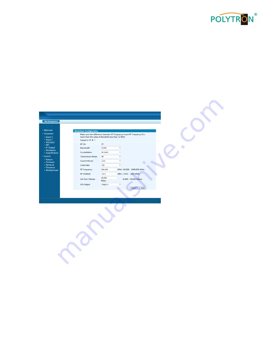
This menu is used to configure the modulators. Up to 2 output channels can be activated and specified. The ASI
data rate and the content of the ASI transport stream are also defined in the modulator menu. The outputs A, B or
the total signal, which consists of the input signals, can be selected as output E as the ASI signal. The signal of the
ASI output ASI OUT 1 is also mirrored on the ASI output ASI OUT 2.
Pic. 23: Configuration of the modulators of the HDS 4 T01
Selection
box “Output (A, B)“
These selection boxes are used to define the output modulator to be configured for the HDS device.
Selection
box „RF On”
This selection box activates the output modulator of the HDS device.
Up to 2 modulators/channels can be activated.
Bandwidth
Defining the bandwidth of the DVB-T channel.
6 MHz, 7 MHz, 8 MHz
Standard: 8 MHz
Constellation
Configuration of the constellation of the output signals.
QPK, 16 QAM, 64 QAM
Standard: 64 QAM
Transmission Mode
Determination of the transmission mode according to the used FFT length.
2K, 8K
Standard: 2K
Guard Interval
Determination of the „Guard Interval“ against propagation delays, echoes and reflections.
1/32, 1/8, 1/16, 1/32
Standard: 1/32
Code Rate
Setting the code rate of the signal.
1/2, 2/3, 3/4, 5/6, 7/8
Standard: 7/8
Содержание HDS 2 C01
Страница 3: ...3 1 Montage und Sicherheitshinweise...
Страница 28: ...28 1 Mounting and safety instructions...
Страница 54: ...54 Notizen Notes...
Страница 55: ...55 Notizen Notes...


