


20
IK-E283-001E
5 Ah
76 hours
7 Ah
108 hours
(25% ageing decrease in the batteries capacity has been considered)
During the control panel configuration, when some current consumption by auxiliary external devices
is considered (especially during the quiescent mode), it is important to take into consideration that
the reserve battery powered device operation time will be accordingly shorter. The battery cluster is
automatically charged by the control panel power supply device.
The efficiency of both the batteries and charging device is continuously monitored and any fault is
being signalled. The battery is recognised as inoperative when its internal resistance (together with
the connection resistance) increases and exceeds 2 Ω.
The battery installation, operation and waste-disposal must be carried out pursuant to the
manufacturer’s manual. A waste battery must be delivered to a proper collecting and recycling point
in accordance with the law in force.
6.2.1 Automatic power supply switch-off
During the control panel operation, being powered only from the battery cluster, the battery voltage
progressively decreases. A reserve power supply voltage drop down to ca. 22 V is acoustically
signalled. Further decline in the battery panel voltage and achieving ca. 21 V level will result in the
control panel automatic switch-off. The power supply renewed switch-on, after a properly charged
battery re-connection, may require pressing of the WŁ.AKU push button which is located inside the
control panel on the printed circuit board.
7 INSTALLATION
7.1 CONTROL PANEL MOUNTING
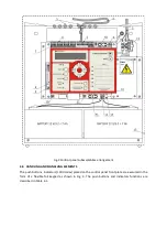
The control panel should to be mounted on a wall using three expansion anchor bolts of minimum
diameter at 8 mm. The spacing of the fastening bolt holes is shown in Fig. 4. The control panel
mounting is possible only without batteries.
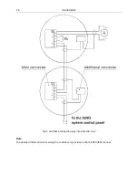
7.2 WIRING
Detection, alarm and controlling lines should be routed according to the commonly applicable
principles used in telecommunications. The lines must be continuous and terminated with end-of-
line resistors. They can be routed alongside high voltage electrical conductors.
The detection line wires can be inserted into the control panel from the installation led in the wall
plaster. They are introduced into the control panel upper part through round bushings: separately
the mains supply wires and low-voltage wires. The terminals of the detection lines and relay outputs
on the printed circuit board are removable what enables easy wire connection. The connection
terminals arrangement and descriptions is presented in Fig.2.


