3.13
MAINTENANCE
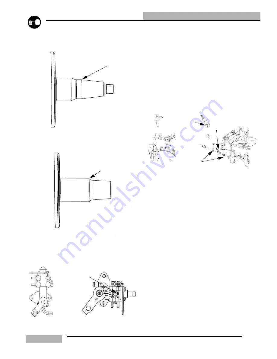
When checking the crankshaft runout on the
MAG
side. Place
the dial indicator end at 1/2
”
(12.7mm) from the bearing flat
(A).
When checking the crankshaft runout from the
PTO
side.
Place the dial indicator end where the taper starts after the
bearing flat (B).
NOTE: Acceptable crankshaft runout (in a crank
fixture) is 0 - .0015
”
(0 - .04mm) on Liberty
t
engines.
0 - .0025
”
(0 - .07mm) on Fuji engines.
OIL PUMP BLEEDING
1.
To aid in bleeding the air out of the oil lines, fill oil
reservoir with the appropriate Polaris injector oil. This will
add pressure to the oil lines.
2.
Loosen the bleed screw (A). After approximately 30
seconds oil should flow from beneath the screw head. This
will indicate the pump is free of the air.
3.
Tighten bleed screw (A) securely.
NOTE: Any time that the engine is disassembled or
repaired, it is important that the oil supply from the
oil pump be checked and full of oil.
IMPORTANT: The oil pump must always be bled
following any service to the oil injection system or
engine.
FITTING TYPES
VERIFYING CHECK VALVE OPERATION
1.
To check the operation of the fittings, fill the oil reservoir,
bleed the pump.
2.
Remove the check valve (A,B) from the component.
3.
Place the oil line (with check valve) in a safe area where no
moving engine part will make contact with it.
4.
Start the engine and let it idle for approximately 1-2
minuets.
5.
Drops of oil should be visible from the check valve after
the engine has idled 1 to 2 minuets, with a drop occurring
every few seconds.
6.
If oil does not flow from one of the check valves, remove
the oil line from the check valve and repeat step 4, if oil is
present during this test replace the faulty check valve.
NOTE: Valves should open with 2-7 lbs of pressure.
NOTE: Install new sealing washers (C) upon
installation on either side of the banjo check valve.
If oil does not flow with the check valves removed from their
feed lines, check the following
• In line filter blocked
• Air may not be bled from the oil pump
• Feed lines leaking
MAG END
1/2”(12.7
A
PTO END
B
PTO END
A
BANJO TYPE
B
C
Содержание SUPERSPORT 2006
Страница 48: ...NOTES SPECIFICATIONS 1 48...
Страница 55: ...2 7 GENERAL SAE TAP DRILL SIZES METRIC TAP DRILL SIZES DECMIAL EQUIVALENTS...
Страница 60: ...2 12 GENERAL SPECIAL TOOLS...
Страница 61: ...2 13 GENERAL...
Страница 62: ...2 14 GENERAL...
Страница 106: ...4 18 CARBURETION...
Страница 139: ...6 27 ENGINE 340 550 ENGINE REBUILDING 10 11 3 4 12 13 5 2 14 1 16 15 16 9 17 6 7 8...
Страница 156: ...7 12 CLUTCHING 1 1 2 3 4 5 6 7 18 17 10 8 9 13 12 11 15 16 14...
Страница 192: ...8 20 FINAL DRIVE...
Страница 200: ...10 2 FRONT SUSPENSION STEERING FUSION IQ RMK 600 RMK Fusion 14 78...
Страница 201: ...10 3 FRONT SUSPENSION STEERING EDGE RMK Apply Polaris All Season Grease to all zerks...
Страница 202: ...10 4 FRONT SUSPENSION STEERING 42 5 EDGE Apply Polaris All Season Grease to all zerks...
Страница 203: ...10 5 FRONT SUSPENSION STEERING WIDETRAK Apply Polaris All Season Grease to all zerks...
Страница 244: ...11 28 REAR SUSPENSION...
Страница 256: ...12 12 CHASSIS HOOD...
Страница 282: ...13 26 ELECTRICAL...
Страница 288: ...13 32 ELECTRICAL...
Страница 289: ...14 1 WIRE DIAGRAM 2006 600 FUSION HO HOOD...
Страница 290: ...14 2 WIRE DIAGRAM 2006 HO RMK HOOD...
Страница 291: ...14 3 WIRE DIAGRAM 600 HO FUSION RMK CHASSIS...
Страница 292: ...14 4 WIRE DIAGRAM 600 HO FUSION RMK CHASSIS CALL OUTS...
Страница 293: ...14 5 WIRE DIAGRAM 700 900 ENGINE...
Страница 294: ...14 6 WIRE DIAGRAM 700 900 ENGINE AND ENGINE CALL OUTS...
Страница 295: ...14 7 WIRE DIAGRAM 700 900 CHASSIS...
Страница 297: ...14 9 WIRE DIAGRAM 340 550 FUJI FAN ENGINE CHASSIS...
Страница 298: ...14 10 WIRE DIAGRAM 500 FUJI ENGINE CHASSIS...
Страница 299: ...14 11 WIRE DIAGRAM 500 600 IBERTY ENGINE CHASSIS...
Страница 300: ...14 12 WIRE DIAGRAM WIDETRAK ENGINE CHASSIS...


