background image

Sirius-3 Navtex 3-Frequency


-

 24 

System configuration - example 

The Sirius-3 Navtex receiver can be customized to suit your 
installation. The following illustration is an example of a system. 


Содержание Sirius-3 Navtex 3-Frequency

Страница 1: ...Sirius 3 Navtex 3 Frequency Sirius 3 GMDSS Tri Channel Navtex Receiver Owner s Installation Manual Version 2 6 ...

Страница 2: ...tices No liability can be accepted for any inaccuracies or omissions in the manual although every care has been taken to make it as complete and accurate as possible This manual applies to Sirius firmware 3383 1 1 2008 Build time December 23 2011 5392 Polaris Electronics A S Kaerholt 1 DK 9210 Aalborg SO Denmark Telephone 45 9631 7900 Fax 45 9631 7901 E mail info polaris as dk Web www polaris as d...

Страница 3: ...Format of Navtex Messages 16 Subject Indicators 17 Installation Manual 18 Sirius 3 Connectors 18 Compass Safe Distance 19 Power Connection 19 Ground Connection 19 Antenna Connection 20 Printer Connection 20 GPS Connection 21 ECDIS Connection 22 Central Mute Connection 22 Alarm Relay Connection 23 AUX Connection 23 System configuration example 24 Firmware Update 25 Warranty and Service 26 Validity ...

Страница 4: ...e equipment is designed for operation in temperatures between 15o C and 55o C Do not use the Navtex receiver in temperatures which exceed this range The Sirius 3 is waterproof from the front only A Navtex receiver is an aid to safe navigation and should not lead to a reduction in the level of good navigation practice The propagation of radio signals may vary over time No liability can be accepted ...

Страница 5: ...t required by the user however some message categories at 518 kHz are mandatory and can therefore not be switched off There is no on off switch as the equipment must always be turned on so that Navtex messages are received even in port If the equipment is installed with an external switch at the main electrical switchboard please be sure that the equipment is turned on at least one hour before dep...

Страница 6: ... Press to enter Setup menu The menu will be described in details on page 8 Press to view a listing of all received messages It is possible to view a single message from the list by touching it Furthermore you can select or deselect 490 and or 4 209 5 kHz messages in the right side You cannot deselect 518 kHz as the monitoring of this frequency is mandatory Press to view a selected message ...

Страница 7: ...d warning will be triggered if Alarm sound is enabled and a red dot will appear in this area Press it to acknowledge To enter the message view menu you can either select a message by touching the text and then press From this menu you can choose to print the message lock the message delete the message or return back to the home screen If a message consists of more than 10 lines you can toggle up a...

Страница 8: ...elect the Coast Stations you want to use for each of the three frequency bands 490 kHz 518 kHz and 4 209 5 kHz All coast stations are enabled by default as shown in the figure above Should you however want to disable all coast stations the mandatory services A B D and L are still received on 518 kHz ...

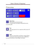
Страница 9: ... by the Delete all messages button Visible messages A maximum of 1 000 messages are selectable however we recommend no more than 400 Delete all messages For safety reasons you have to confirm your choice Notice that locked messages cannot be deleted here System Settings The menu will be described in details on page 10 About Contains information about firmware version etc Home Press this button to ...

Страница 10: ...afety reasons the display settings will be reset at every power cycle Time Adjust date and time if not connected to GPS or other UTC source Sound Choose if sound should be on off when messages alarms are received or when using touch screen Furthermore you can see the status of Central Muting if connected ...

Страница 11: ... single message can be printed by pressing in the message view menu Use the Cut paper button to switch ON OFF the internal knife in the printer ECDIS From this menu a connection to an ECDIS system can be enabled or disabled Press the Send test button to test the connection to the ECDIS system If the ECDIS system doesn t send acknowledgements press the Ignore ACK button ...

Страница 12: ... If a printer is connected you can press to print a position label with UTC Time and Date These labels are useful when you write positions in the logbook or in case of an emergency Turn antenna power on or off Red light indicates that antenna power is turned off and green light that it is turned on ...

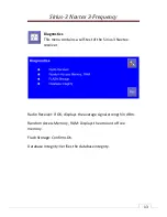
Страница 13: ...contains a self test of the Sirius 3 Navtex receiver Radio Receiver If OK displays the average signal strength in dBm Random Access Memory RAM Displays the amount of free memory Flash Storage Confirms OK Database Integrity Verifies the database integrity ...

Страница 14: ...Frequency 14 Declaration of Conformity A Declaration of Conformity is downloadable from our web site http www polaris as dk files certificates sirius ec_declaration_of_conformity_polaris _bureau_veritas_signed_270410 pdf ...

Страница 15: ...Sirius 3 Navtex 3 Frequency 15 Green Passport A Green Passport is downloadable from our web site http www polaris as dk Default asp Action Details Item 835 ...

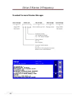
Страница 16: ...Sirius 3 Navtex 3 Frequency 16 Standard Format of Navtex Messages ...

Страница 17: ... E Meteorological Forecasts F Pilot Service Messages G Available H LORAN Messages I Available J SATNAV Messages K Other Electronic Navaid Messages L Navigation Warnings other than A V Special Services W Special Services X Special Services Y Special Services Z No Message on hand Services A B D and L for 518 KHz cannot be rejected by the receiver ...

Страница 18: ...Sirius 3 Navtex 3 Frequency 18 Installation Manual The Sirius 3 Navtex receiver package includes Sirius 3 Navtex receiver 1 5 m Power Cable User Installation Manual Test Sheet Sirius 3 Connectors ...

Страница 19: ...d black to It is recommended to include a fuse in the power supply The male power plug can be mounted in the right female connector only PWR Connector pin out Pin Number Connection Notes 1 V Ship s Supply 12 24 V DC 2 V Ship s Supply 12 24 V DC 3 NC No Connection 4 V Ship s Supply V 5 V Ship s Supply V 6 V Ship s Supply 12 24 V DC 7 NC No Connection 8 NC No Connection 9 V Ship s Supply V Ground Co...

Страница 20: ...igned for NA 3S Active Antenna but you can use a passive whip antenna as well If you connect an active antenna remember to enable antenna power When the indicator turns green the Sirius 3 supplies voltage through the coax cable If you connect a passive antenna make sure that antenna power is turned off Printer Connection A USB printer P N SIR PRN can be connected to the Sirius 3 If you connect a P...

Страница 21: ...n a GPS is connected UTC is automatically updated Sirius 3 will receive the information from these NMEA sentences RMC Time and Date GGA Position NMEA 0183 port pin out Pin Number Connection Notes 1 GND Ground 2 NC No Connection 3 NC No Connection 4 TX Option 5 TX Option 6 NC No Connection 7 NC No Connection 8 RX NMEA 0183 Input 9 RX NMEA 0183 Input ...

Страница 22: ... be connected to pin 2 and 6 It will be enabled by a connection between the two pins CRNRX 003 001 01 TD02 0 044113 24 12 2011 097 0 A 13 CRNRX 003 002 01 0D 0AISSUED ON SATURDAY 12 DECEMBER 2011 6D CRNRX 003 003 01 0D 0ASIRIUS3 TEST MESSAGE 0D 0A 31 CRALR 044113 051 A V NAVTEX Test button pressed 0E CRNRX 002 001 02 RD15 3 044329 24 12 2011 062 0 A 0A1 2 3 4 5 6 7 8 9 0 A B 1E CRNRX 002 002 02 C ...

Страница 23: ... pin 3 and 7 is made ECDIS port Alarm Relay and Mute pin out Pin Number Connection Notes 1 GND Ground 2 Mute A Mute Input 3 Alarm com Alarm relay 4 TX IBS port Output 5 TX IBS port Output 6 Mute B Mute Input 7 Alarm No Alarm relay 8 RX IBS port Input 9 RX IBS port Input AUX Connection This port is used for special applications only ...

Страница 24: ...Sirius 3 Navtex 3 Frequency 24 System configuration example The Sirius 3 Navtex receiver can be customized to suit your installation The following illustration is an example of a system ...

Страница 25: ... update is required please download the firmware image to the root of a FAT32 formatted USB memory stick Mount the USB memory stick in the USB port power cycle the unit and follow the instructions on the screen Do not interrupt firmware update during the process ...

Страница 26: ...ny other costs are the responsibility of the customer Maximum liability shall not in any case exceed the contract price of the products claimed to be defective On Board Service can be arranged by Polaris Electronics A S or local service dealers upon request Expenses associated with replacement of the defective modules parts on board time overtime travel lodging per diem insurance duties or any oth...

Страница 27: ...nstallation use or repair of the product Consequential damages include but are not limited to any loss of profit property damage or personal injury The terms of warranty as described does not affect your statutory rights All enquiries relating to this warranty or approved service agents should be sent to Polaris Electronics A S Telephone 45 9631 7900 Kaerholt 1 Fax 45 9631 7901 DK 9210 Aalborg SO ...

Страница 28: ...Sirius 3 Navtex 3 Frequency 28 ...

Отзывы: