8.11
Steering and Suspensions
8
Rod Ends
Rod ends must be parallel to their respective mounting surface
after tightening jam nut. If possible, support the edge of the rod
end to keep it from rotating out of position until jam nut is tight.
When rod ends are properly tightened, the rod should rotate
freely approximately 1/8 turn.
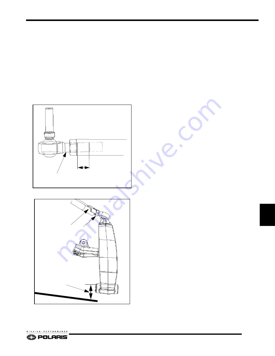
Rod End Engagement
Rod ends must engage the rod a minimum of 2x the thread
diameter when adjustment is complete.
Example: .4375” (11mm) rod end (A) X 2 = minimum thread
engagement (B) .875” (22mm).
Camber Adjustment
1.
Raise the front of the machine so that the skis are off the
floor 3” (7.62cm). The shocks should be at full extension
2.
Remove the skis.
3.
Determine which spindle requires the greatest amount of
correction my installing the alignment bar through one
spindle to the other spindle. Measure the distance from the
top of the alignment bar to the top of the ski mount hole with
the bushing(s) removed. Record measurement.
4.
Remove the alignment bar and install it to measure the
opposite side. Measure the distance from the top of the
alignment bar to the top of the ski mount hole with the
bushing(s) removed. Record measurement
5.
To adjust the camber, unlock the lock nut and adjust the
camber with the adjuster nut until alignment bar
measurement is within the specified range for each spindle.
6.
Once the specification is achieved, tighten all jam nut(s)
and torque them Ft.Lb. (61 Nm).
7.
Re-check the set up width and compare to specification.
Handlebar Centering
1.
Raise the front of the machine off the floor so that the
spindles are off the floor 3
”
(7.62cm).
2.
Insert the alignment bar through both ski bolt holes in each
spindles.
3.
Adjust Toe until handlebar is centered.
Toe Adjustment
Toe is adjusted with the shocks and skis installed. Track
alignment must be correct before starting this process.
Toe alignment is measured at ride height.
1.
Lift front of the machine off the floor rock the front end up
and down and then set it down gently. This will set the unit
at ride height.
2.
Measure and make a mark 10
”
(2.54cm) forward of the ski
mount bolt and 10
”
(2.54cm) behind the ski mount bolt,
preferably on the center line of the carbide skags.
3.
Place a straight edge along the one side of the track. Make
sure that the straight edge is touching along the length of
the track.
A
B
2
1
3
Содержание FST IQ 2007
Страница 45: ...NOTES Model Specifications 1 42 ...
Страница 57: ...NOTES General Information 2 12 ...
Страница 79: ...NOTES Maintenance 3 22 ...
Страница 84: ...4 5 Fuel Systems 4 Carbureted Fuel System Typical ...
Страница 88: ...4 9 Fuel Systems 4 Throttle Opening Vs Fuel Flow VM only ...
Страница 101: ...4 22 Fuel Systems Chassis Relay ...
Страница 103: ...4 24 Fuel Systems Vehicle Speed Sensor ...
Страница 119: ...NOTES Fuel Systems 4 40 ...
Страница 183: ...NOTES Final Drive and Brakes 6 16 ...
Страница 203: ...NOTES PVT System 7 20 ...
Страница 296: ...11 11 Battery and Electrical Systems 11 ELECTRIC START IQ CARBURETED CFI System Schematic 600 Carbureted ...
Страница 297: ...11 12 Battery and Electrical Systems System Schematic CFI ...
Страница 305: ...NOTES Battery and Electrical Systems 11 20 ...
Страница 310: ...12 1 Wiring Diagrams 2007 600 HO Carbureted 1 of 2 ...
Страница 311: ...12 2 Wiring Diagrams 2007 600 HO Carbureted 2 of 2 ...
Страница 312: ...12 3 Wiring Diagrams 2007 600 HO Carbureted Hood Harness ...
Страница 313: ...12 4 Wiring Diagrams 2007 600 700 CFI Chassis Harness 1 of 2 ...
Страница 314: ...12 5 Wiring Diagrams 2007 600 700 CFI Chassis Harness 2 of 2 ...
Страница 316: ...12 7 Wiring Diagrams 2007 600 700 CFI Engine Harness ...
Страница 317: ...12 8 Wiring Diagrams 2008 IQ Shift 1 of 2 ...
Страница 318: ...12 9 Wiring Diagrams 2008 IQ Shift 2 of 2 ...
Страница 319: ...12 10 Wiring Diagrams 2008 IQ Shift Hood Harness ...
Страница 320: ...12 11 Wiring Diagrams 2008 IQ Shift RMK 1 of 2 ...
Страница 321: ...12 12 Wiring Diagrams 2008 IQ Shift RMK 2 of 2 ...
Страница 322: ...12 13 Wiring Diagrams 2008 IQ Shift RMK Hood Harness ...
Страница 323: ...12 14 Wiring Diagrams 2008 IQ CFI Chassis Harness 1 of 2 ...
Страница 324: ...12 15 Wiring Diagrams 2008 IQ CFI Chassis Harness 2 of 2 ...
Страница 325: ...12 16 Wiring Diagrams 2008 IQ CFI Engine Harness ...


