background image

OPERATION

12

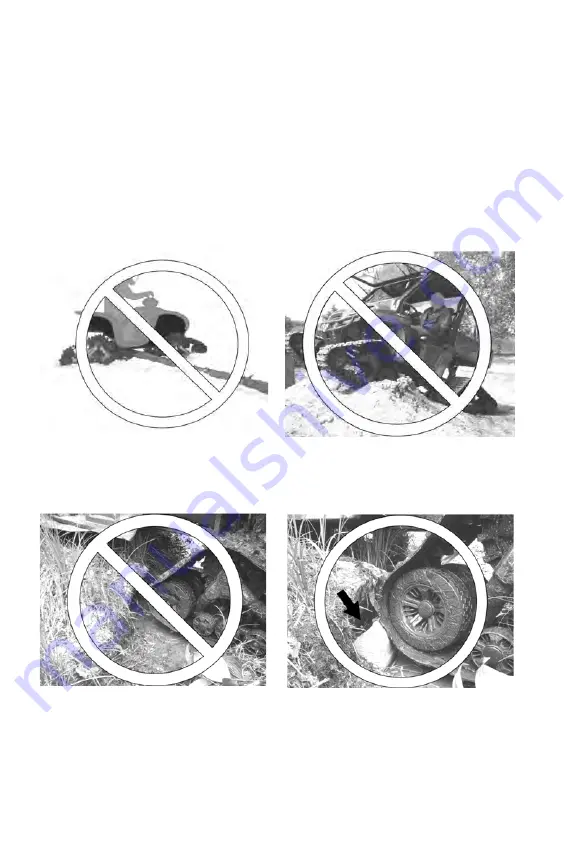
Driving Over Obstacles

Obstacles are not always visible, especially in areas with deep snow or 
mud. Avoid operating in areas that are likely to contain hidden obstacles. 
Refer to your vehicle owner’s manual for proper operating procedures 
when driving over obstacles.

Do not attempt to operate over large obstacles, such as large rocks, tree 
trunks, stumps or steep ridges. Large obstacles may lodge between the 
front and rear track systems and immobilize the vehicle.

Do not attempt to operate over obstacles more than 12 inches (30.5 cm) 
in height. If unavoidable, always place a smaller log or rock near the 
obstacle to serve as a ramp for the track.

Содержание 9925638

Страница 1: ...UTV TRACK SYSTEM PROSPECTOR PRO 2016 USER MANUAL 9925638 ...

Страница 2: ... publication Due to constant improvements in the design and quality of production components some minor discrepancies may result between the actual vehicle and the information presented in this publication Depictions and or procedures in this publication are intended for reference use only No liability can be accepted for omissions or inaccuracies Any reprinting or reuse of the depictions and or p...

Страница 3: ...4 Safety 6 Operation 7 Installation Removal Re Installation 15 Adjustments 18 Rubber Track Installation 26 Track System Break In 27 Maintenance 28 Troubleshooting 40 CE Declaration of Conformity 41 Service kits 42 P N 9925638 VERSION D ...

Страница 4: ...s situation that if not avoided will result in death or serious injury WARNING A WARNING indicates a hazardous situation that if not avoided could result in death or serious injury CAUTION A CAUTION indicates a hazardous situation that if not avoided could result in minor or moderate injury NOTICE A NOTICE indicates a situation that could result in property damage The Prohibition Safety Sign indic...

Страница 5: ...Understand all safety warnings precautions and operating procedures before operating a POLARIS vehicle equipped with the track system Keep this manual with the vehicle If track systems are sold or transferred to a new user the user manual must also be transferred to the new user Always follow all inspection and maintenance procedures described in this user manual and in the track kit installation ...

Страница 6: ...rnings precautions and operating procedures before operating a POLARIS vehicle equipped with a PROSPECTOR PRO track system Keep this manual with the vehicle If track systems are sold or transferred to a new user the user manual must also be transferred to the new user MOVING PARTS Moving parts can crush and cut Keep hands and body clear of moving parts Turn the engine off before servicing track sy...

Страница 7: ...ff trails in remote terrain always carry survival equipment appropriate to the conditions you may encounter Such equipment may include but is not limited to a shovel a first aid kit extra clothing a sleeping bag a flashlight food and water a signaling mirror a means of building a fire and a two way radio or cellular telephone If possible carry essential spare parts for emergency repairs 1 Inspect ...

Страница 8: ...erate with extra caution on rough terrain 5 Operate the vehicle in 4X4 mode when operating with tracks This will significantly reduce the possibility of derailing 6 The vehicle will handle differently when a track system is installed Select an open area that allows room to familiarize yourself with vehicle operation and handling Drive slowly at first On level surfaces practice starting stopping tu...

Страница 9: ...s 11 Travel slowly and use extra caution when operating on unfamiliar terrain Not all obstacles are immediately visible 12 When driving in deep snow avoid spinning the tracks which could cause the vehicle to become stuck When under power tracks will continue to turn in deep snow even if the vehicle fails to move 13 When driving in snow allow for a greater braking distance Periodically apply the br...

Страница 10: ...her stress on steering and track systems which can lead to component damage and result in an accident or rollover If making a steep descent is unavoidable drive straight downhill Avoid making turns during steep descents Towing a Stuck Vehicle If your track equipped vehicle must be towed from deep snow always tow in the opposite direction of vehicle travel Do not attempt to tow the vehicle in the s...

Страница 11: ...hind the tracks or use a shovel to clear away the snow POLARIS does not recommend backing downhill with this vehicle Refer to your vehicle owner s manual for proper operating pro cedures when driving on inclines If backing downhill is unavoidable back slowly and back straight downhill If the vehicle becomes stuck in snow while backing downhill avoid towing or operating the vehicle rearward as dama...

Страница 12: ...er operating procedures when driving over obstacles Do not attempt to operate over large obstacles such as large rocks tree trunks stumps or steep ridges Large obstacles may lodge between the front and rear track systems and immobilize the vehicle Do not attempt to operate over obstacles more than 12 inches 30 5 cm in height If unavoidable always place a smaller log or rock near the obstacle to se...

Страница 13: ...he track systems Sharp Turns in Locked Differential 4X4 Mode Never make sharp turns in locked diffential 4X4 mode on a sticky terrain without lubrication The track system is designed to slip into the drive system preventing the vehicle from being overloaded NOTE Somes vehicles do not have unlocked 4X4 mode on the rear differential These vehicles should avoid the situation described above and take ...

Страница 14: ...hile loading or unloading the vehicle into a truck box if it snags or catches the tailgate latch post Carefully observe track clearance on both sides of the vehicle while loading or unloading the vehicle Use caution when operating near extended bolts bars or similar appendages that could cause tears to a moving track Attempting jumps and other stunts increases the risk of an accident or rollover N...

Страница 15: ... Never place body parts under an elevated vehicle unless the vehicle is properly immobilized on appropriate stands Track System Installation CAUTION Hot exhaust system parts can cause burns Allow components to cool sufficiently before proceeding Initial Installation POLARIS recommends having your authorized POLARIS dealer perform the initial installation of a track system 1 Install the track syste...

Страница 16: ...atproperly on soiled hubs 4 Reinstall the rear track systems then reinstall the front track systems 5 Tighten fasteners in a criss cross pattern to the manufacturer s recommended torque specification Refer to your vehicle owner s manual or service manual 6 After the initial installation and after every future reinstallation of the tracks always adjust track angle of attack system alignment and tra...

Страница 17: ...tall the wheels Make sure all original components that were removed for track installation are reinstalled properly for wheeled operation Refer to your vehicle owner s manual or service manual Off Vehicle Track System Storage 4 Remove the anti rotation bracket cover 1 Remove the anchor bracket 2 from the suspension arm but leave it attached to the anti rotation device on the track system The brack...

Страница 18: ...llowing procedure Refer to the track kit installation instructions for more information as needed Perform steps 3 6 for both front track systems 1 Position the vehicle on a level surface 2 Stop the engine 3 Using the handlebars or steering wheel make sure the tracks are in the straight ahead position 4 Verify that the stabilizing arm 1 is attached to the front anchor bracket 2 5 Verify that the sp...

Страница 19: ...istance from bar to ground will result in easier steering but will produce a wobbling effect at high speeds Decreasing the distance from bar to ground will result in harder steering but will provide more stability at higher speeds 8 If adjustment is necessary loosen the jam nut 1 9 Rotate the stabilizing arm 3 to adjust the length of the rod end 2 Adjust until the distance measurement from the fla...

Страница 20: ...k systems 1 Verify that the stabilizing arm 1 is attached to the rear anchor bracket 2 2 Verify that the spring assembly bolt 3 is tightened to specification Torque 29 5 ft lbs 40 Nm 3 Verify that stabilizing arm components are installed in the correct order Refer to the track kit installation instructions for more information as needed 4 Loosen the anti rotation bracket bolts 1 and 2 to allow the...

Страница 21: ...ngle to perpendicular to the stabilizing rod Tighten the two anti rotation bracket mounting bolts 1 and 2 Torque 37 ft lbs 50 Nm 7 Turn the stabilizing arm nut to adjust the length of the rod end so that the rubber cone 2 applies light pressure on the anti rotation retainer 3 Tip A wider gap at the rubber cone bushing provides better obstacle climbing and flotation capability in powdered snow whil...

Страница 22: ...lignment Alignment Inspection 1 Operate the vehicle in a straightahead direction for approximately 10 ft 3 m Stop the vehicle on a level surface 2 Stop the engine Place the transmission in park if equipped or in forward gear Engage the park brake if equipped 3 Perform the following measurements on the front track systems Measure the distance between the two front inner 241mm wheels A Measurement A...

Страница 23: ...measurement B from measurement A The result must be 0 to 1 8 inch 0 3 mm If the result is not within this range adjust alignment See page 24 NOTE Adjustments will be easier and more precise if you begin when measurement A is greater than measurement A B 0 to 1 8 inch 0 to 3 mm ...

Страница 24: ...ar Apply the recommended force 1 to measure deflection 2 Refer to the chart below for track tension data If adjustment is needed see page 25 2 Screw or unscrew the coupling rods 2 equally on both sides of the vehicle 3 Tighten the lock nuts to specification Refer to your vehicle specific service manual 4 To verify the adjustment operate the vehicle in reverse for 15 20 feet 5 6 m then repeat steps...

Страница 25: ...nut 1 2 Turn the tensioner rod adjustment nut 2 clockwise or counter clockwise as needed to adjust tension to the recommended specification Tip Higher rubber track tension reduces the risk of derailing and reduces drive ratcheting Lower rubber track tension provides better performance better rolling and better fuel economy 3 When adjustment is complete tighten the jam nut 1 securely against the ad...

Страница 26: ...d jam nut and adjusting nut to slide the tensioner assembly to the mini mum position 5 Remove the two 9 5 inch 241 mm wheels from the track ten sioner 7 Install the rubber track Rear tracks can be installed in both directions of rotation For front tracks a mark on the track indicates correct orientation 8 Reinstall the two wheels 9 Adjust track tension See page 24 NOTE In applications where instal...

Страница 27: ...as on asphalt or on hay or straw fields Operate the vehicle in a lubricated environment water mud snow soft soil sand dust and similar terrain Failure to operate in these conditions during break in can result in smoke and odor from rubber components as well as plastic deposits on the sprocket and or frame Operate below 6 MPH 10 km h when making sharp turns Break In Inspection Chart Item Inspection...

Страница 28: ...r of the track systems until the vehicle is stopped the engine is off and the park brake is engaged if equipped We recommend having your dealer perform all track system service and alignment procedures For vehicles subjected to normal use refer to the chart on page 29 For vehicles subjected to severe or heavy use refer to the maintenance chart on page 30 Task Definitions Refer to the following tas...

Страница 29: ...t Adjust Wear 31 Inspect WHEELS Side Wear 31 Inspect Replace Bearings 31 Inspect Inspect Replace Seal Lubrication 31 Inspect Lubricate Lubricate FRAME Hub Bearings 32 Inspect Replace Hub Bearing Seal 32 Lubricate Inspect Lubricate Track Guide Wear 32 Inspect Replace Stabilizers 32 Inspect Replace Cracks 32 Clean Inspect SPROCKET Wear 32 Clean Inspect ANTI ROTATION Lubrication 32 Clean Lubricate Cl...

Страница 30: ... Adjust Inspect Adjust Wear 31 Inspect WHEELS Side Wear 31 Inspect Replace Bearings 31 Inspect Inspect Replace Seal Lubrication 31 Inspect Lubricate Lubricate FRAME Hub Bearings 32 Inspect Replace Hub Bearing Seal 32 Lubricate Inspect Lubricate Track Guide Wear 32 Inspect Replace Stabilizers 32 Inspect Replace Cracks 32 Clean Inspect SPROCKET Wear 32 Clean Inspect ANTI ROTATION Lubrication 32 Clea...

Страница 31: ...ritical bolts as identified in the Exploded Views section of this manual beginning on page 42 Tighten any loose bolts to specification using a high strength threadlocker such as Loctite 263 Do not over tighten Track Maintenance 1 Verify track tension Adjust as needed See pages 24 25 2 Inspect tracks for wear or damage See page 38 A worn or damaged track can result in premature wear of system compo...

Страница 32: ...the stabilizer assembly of the front track systems and rear track systems If cone bores show oval shaped wear replace the cones Use new bolts and washers 5 Inspect frames for cracks or defects Damaged components can impair proper operation of the systems Replace any damaged components Sprocket Maintenance Inspect sprockets for wear See page 37 Replace worn sprockets Anti Rotation Maintenance 1 Cle...

Страница 33: ...o the owner s manual or service manual for your vehicle Special tool usage Some components require special tools for servicing Always use the appropriate tools to avoid damage to components Pressure Washer Use If a high pressure water system is used for cleaning not recommended exercise extreme caution The water may damage components Avoid directing the water stream at wheel bearing seals and rubb...

Страница 34: ...mmend the use of a high quality water resistant anti friction grease A 132 mm Wheel Bearing Seal Apply 1 1 5 cc of grease evenly on and between the wheel bearing seal lips Apply over the entire circumference B 241 mm Wheel Bearing Seal Apply 1 1 5 cc of grease evenly on and between the wheel bearing seal lips Apply over the entire circumference A B ...

Страница 35: ...entire circumference of the seal IMPORTANT Make sure the hub seal is installed flush with the hub face It should not extend beyond the hub face F Hub Speed Sleeve Apply 1 1 5 cc of grease over the entire width and circumference of the sleeve G Frame Tubing Tensioner Side Slide the tensioner to its furthest point out Apply evenly a thin coat of grease oil or spray lubricant on the outside of the te...

Страница 36: ...lizer shaft through the grease fitting Do not overfill The protective plastic cap could be forced off I Stabilizing Arms Apply spray lubricant around the compression spring and over its entirelength on both front and rear track systems Front Rear I Stabilizing Arms Apply spray lubricant to rod end H I I ...

Страница 37: ... than 1 75 inches 45 mm Excessively worn wheels will not offer enough support for track guidance Inspect for wheel wear especially on the interior guiding strips 1 and between the wheel profiles 2 Replace a wheel if the inner surface is worn out or if cracks appear between the wheel profiles Sprocket wear Replace if 3 4 in 19 mm Excessive sprocket wear could lower track drive efficiency and reduce...

Страница 38: ...cave shape of the guiding strip is no longer visible Track Wear Operating with a worn or damaged track could result in damage to the wheels and to the track guide Inspect track condition on both the inner and outer sides of the track Inspect the rolling path the driving lug and the profile Inspect the entire length and width of the track for wear cracks and other damage If a track s internal struc...

Страница 39: ... affect track system performance Inspect the anti rotation system for wear especially at the ball joint Make sure the ball joint is neither seized nor extremely loose Make sure the ball rotates freely in the housing 1 Make sure there is not excessive play between the ball and housing 2 ...

Страница 40: ...ts burned rubber odor Blocked wheel Attempt to free wheel replace if necessary Incorrect system alignment Adjust system alignment See pages 22 23 Constant turning Vary turning radius operate in lubricated environment Constant operation in ruts Exit ruts occasionally to vary direction operate in lubricated environment Loss of power Track tension too high Lower track tension Clean mud snow other bui...

Страница 41: ... THE PRODUCT SERIES PRODUCT Polaris Prospector Pro UTV CUSTOMER IS IN CONFORMITY WITH THE FOLLOWING STANDARDS NUMBER TITLE DATE EN 62079 Preparation of Instruction 2001 EN 12100 1 2 Safety of Machinery 1996 EN 17050 1 2 Conformity Assessment 2005 AND IN CONFORMITY WITH THE FOLLOWING EC DIRECTIVE NUMBER TITLE DATE 2006 42 EEC Safety of machinery directives 2006 DONE AT Shawinigan QC Canada PERSON I...

Страница 42: ...TUBE DIA EXT 1 3 4 PO 1 4 2 LIPS CAP 2 O D TUBE BOUCHON 2 LÈVRES TUBE DIA EXT 2 PO 1 5 CAP NUT CAPUCHON DE BOULON 1 6 HUB CAP POLARIS ASSY CAP DE MOYEU POLARIS 1 7 HSBS M6 1X10 10 9 ZP 1 8 HFCS M8 1 25X70 10 9 ZP IFI536 1 9 CP 1 8 1 3 4 ZP 1 10 SDSQWS 12 24X1 5 ZP 7 11 TENSIONNER BUSHING COUSSINET TENSIONNEUR 1 12 W 9 9X6X0 9 AL 1 13 FNN M8 1 25 8 ZP DIN6926 1 14 TENSIONNER ROD HEX NUT ASS Y ENS T...

Страница 43: ...N DE BOULON 1 6 HUB CAP POLARIS ASSY CAP DE MOYEU POLARIS 1 7 HSBS M6 1X10 10 9 ZP 1 8 HFCS M8 1 25X70 10 9 ZP IFI536 1 9 CP 1 8 1 3 4 ZP 1 10 SDSQWS 12 24X1 5 ZP 7 11 TENSIONNER BUSHING COUSSINET TENSIONNEUR 1 12 W 9 9X6X0 9 AL 1 13 FNN M8 1 25 8 ZP DIN6926 1 14 TENSIONNER ROD HEX NUT ASS Y ENS TIGE TENSIONNEUR ÉCROU HEX 1 15 STICKER ALIGNMENT AUTOCOLLANT ALIGNEMENT 1 16 STICKER WARNING AUTOCOLLA...

Страница 44: ...ON DE BOULON 1 6 HUB CAP POLARIS ASSY CAP DE MOYEU POLARIS 1 7 HSBS M6 1X10 10 9 ZP 1 8 HFCS M8 1 25X70 10 9 ZP IFI536 1 9 CP 1 8 1 3 4 ZP 1 10 SDSQWS 12 24X1 5 ZP 7 11 TENSIONNER BUSHING COUSSINET TENSIONNEUR 1 12 W 9 9X6X0 9 AL 1 13 FNN M8 1 25 8 ZP DIN6926 1 14 TENSIONNER ROD HEX NUT ASS Y ENS TIGE TENSIONNEUR ÉCROU HEX 1 15 STICKER ALIGNMENT AUTOCOLLANT ALIGNEMENT 1 16 STICKER WARNING AUTOCOLL...

Страница 45: ...ON DE BOULON 1 6 HUB CAP POLARIS ASSY CAP DE MOYEU POLARIS 1 7 HSBS M6 1X10 10 9 ZP 1 8 HFCS M8 1 25X70 10 9 ZP IFI536 1 9 CP 1 8 1 3 4 ZP 1 10 SDSQWS 12 24X1 5 ZP 7 11 TENSIONNER BUSHING COUSSINET TENSIONNEUR 1 12 W 9 9X6X0 9 AL 1 13 FNN M8 1 25 8 ZP DIN6926 1 14 TENSIONNER ROD HEX NUT ASS Y ENS TIGE TENSIONNEUR ÉCROU HEX 1 15 STICKER ALIGNMENT AUTOCOLLANT ALIGNEMENT 1 16 STICKER WARNING AUTOCOLL...

Страница 46: ... ITEM PART DESCRIPTION QTY E 2205433 K SPROCKET CMPLST 18 TOOTH 1 1 SPROCKET CMPLST XP 18 TOOTH BARBOTIN CMPLST XP 18 DENTS 1 2 HFSCS M10 1 5X30 10 9 ZP TL DIN6921 4 ITEM PART DESCRIPTION QTY F 2205432 K SPROCKET CMPLST 20 TOOTH 1 1 SPROCKET CMPLST XP 20 TOOTH BARBOTIN CMPLST XP 20 DENTS 1 2 HFSCS M10 1 5X30 10 9 ZP TL DIN6921 4 ...

Страница 47: ...KITS 47 Exploded Views 32mm Hub Kit Ensemble moyeu 32 mm ITEM PART DESCRIPTION QTY G 2205870 K HUB CMPLST 32mm 1 1 HUB CMPLST XP HD 32mm ASSY 1 2 HFSCS M10 1 5X30 10 9 ZP TL DIN6921 4 3 ERR 35 2 4 ZP SHR 137 1 ...

Страница 48: ...ION QTY H 2205127 K WHEEL CMPLST MID UTV 1 1 HD WHEEL ASSY ROUE HD ASSEMBLÉE 132mm X 50mm 1 2 WHEEL CAP CAP DE ROUE 1 3 HCSW M10 1 5X25 8 8 ZP TL DIN933 1 ITEM PART DESCRIPTION QTY i 2205447 K WHEEL CMPLST IDLER UTV 1 1 WHEEL ASSY ROUE ASSEMBLÉE UTV 241 MM 1 2 WHEEL CAP CAP DE ROUE 1 3 HCSW M10 1 5X25 8 8 ZP TL DIN933 1 ...

Страница 49: ...X 50mm 2 3 WHEEL CAP CAP DE ROUE 2 4 HCSW M10 1 5X25 8 8 ZP TL DIN933 2 5 URETHANE CONE STABILIZER CÔNE URÉTHANE STABILISATEUR 1 ITEM PART DESCRIPTION QTY K 2205126 K ROCKER CMPLST INNER UTV 1 1 UTV STABILIZER FEMALE ASS Y STABILISATEUR UTV ASSEMBLÉ FEMELLE 1 2 DUST CAP STABILIZER CAPUCHON STABILISATEUR 1 3 HCS M10 1 5X45 10 9 ZP TL DIN931 1 4 TANDEM T BUSHING COUSSINET TANDEM 1 5 W 7 16X1 0X0 072...

Страница 50: ...JOINT D ÉTANCHÉITÉ ARBRE MOYEU 50 x 62 x 10 TC 1 ITEM PART DESCRIPTION QTY M 2205445 K TRACK ADJUSTER CMPLST UTV 1 1 TENSIONER TENSIONNEUR UTV 1 2 2 LIPS CAP 1 3 4 O D TUBE BOUCHON 2 LÈVRES TUBE DIA EXT 1 3 4 PO 1 3 CAP NUT CAPUCHON DE BOULON 1 4 HFCS M8 1 25X70 10 9 ZP IFI536 1 5 CP 1 8 1 3 4 ZP 1 6 TENSIONNER BUSHING COUSSINET TENSIONNEUR 1 7 FNN M8 1 25 8 ZP DIN6926 1 8 TENSIONNER ROD HEX NUT A...

Страница 51: ...de Kit Ensemble guide chenille arrière ITEM PART DESCRIPTION QTY N 2205443 K HYFAX CMPLST FRONT UTV 1 1 SDSQWS 12 24X1 5 ZP 7 2 TRACK GUIDE FRONT GUIDE CHENILLE AVANT 1 ITEM PART DESCRIPTION QTY O 2205444 K HYFAX CMPLST REAR UTV 1 1 SDSQWS 12 24X1 5 ZP 7 2 TRACK GUIDE REAR GUIDE CHENILLE ARRIÈRE 1 ...

Страница 52: ...ION TUBING WELDMENT TUBE ANTI ROTATION COURT SOUDÉ 1 2 HCS M10 1 5X60 10 9 ZP DIN931 1 3 HFSCS M12 1 75X50 8 8 ZP DIN6921 1 4 X LONG ROD END TIGE À ŒIL X LONG 1 5 ROD END SPACER ESPACEUR EMBOUT À ROTULE 2 6 W 374X13X3 ZP DIN 9021 1 7 W 7 16X1 0X0 072 8 ZP USS 1 8 FNN M10 1 5 8 ZP DIN6926 1 9 STABILIZING ROD SPRING RESSORT BRAS STABILISATEUR 1 10 RUBBER DAMPER AMORTISSEUR DE CAOUTCHOUC 1 ...

Страница 53: ...I ROTATION LONG SOUDÉ 1 2 HCS M10 1 5X80 10 9 ZP DIN931 1 3 HFSCS M12 1 75X50 8 8 ZP DIN6921 1 4 X LONG ROD END TIGE À ŒIL X LONG 1 5 ROD END SPACER ESPACEUR EMBOUT À ROTULE 1 6 SPACER ANTI ROTATION ESPACEUR ANTI ROTATION 1 7 W 7 16X1 0X0 072 8 ZP USS 1 8 W 374X13X3 ZP DIN 9021 1 9 FNN M10 1 5 8 ZP DIN6926 1 10 COMPRESSION SPRING LONG RESSORT COMPRESSION LONG 480LBS IN 1 11 RUBBER DAMPER AMORTISSE...

Страница 54: ... 8 8 ZP TL DIN933 8 5 HCS M10 1 5X45 10 9 ZP TL DIN931 1 6 HFCS M8 1 25X70 10 9 ZP TL IFI536 1 7 HFSCS M10 1 5X30 10 9 ZP DIN6921 6 8 CP 1 8 1 3 4 ZP 1 9 SDSQWS 12 24X1 5 ZP 7 10 TANDEM T BUSHING COUSSINET TANDEM 1 11 TENSIONER BUSHING COUSSINET TENSIONNEUR 1 12 W 7 16X1 0X0 072 8 ZP USS 3 13 W 9 9X6X0 9 AL 1 14 FNN M8 1 25 8 ZP DIN6926 1 15 URETHANE CONE STABILIZER CÔNE URÉTHANE STABILISATEUR 2 1...

Страница 55: ...VERSAL ANTI ROT IS PLAQUE PRINCIPALE UNIV ANTI ROT SI 1 2 HCS M10 1 5X80 10 9 ZP DIN931 2 3 W 25X11X2 8 ZP USS 4 4 FNN M10 1 5 8 ZP DIN69261 2 5 RETAINER ANTIROTATION ANTI ROTATION PLAQUE PIVOTANTE 1 ITEM PART DESCRIPTION QTY T 2205449 K HDWR ANTI ROTATION SHORT 1 1 HCS M10 1 5X60 10 9 ZP DIN931 1 2 ROD END SPACER BAGUE ESPACEUR EMBOUT À ROTULE 2 3 W 7 16X1 0X0 072 8 ZP USS 1 4 FNN M10 1 5 8 ZP DI...

Страница 56: ...10 9 ZP DIN931 1 2 ROD END SPACER BAGUE ESPACEUR EMBOUT À ROTULE 1 3 SPACER ANTI ROTATION ESPACEUR ANTI ROTATION 1 4 W 7 16X1 0X0 072 8 ZP USS 1 5 FNN M10 1 5 8 ZP DIN6926 1 ITEM PART DESCRIPTION QTY V 2205453 K DECALS CMPLST UTV 1 1 STICKER ALIGNMENT AUTOCOLLANT ALIGNEMENT 1 2 STICKER WARNING AUTOCOLLANT AVERTISSEMENT 1 3 HUB CAP POLARIS ASSY CAP DE MOYEU POLARIS ASSEMBLÉ 1 4 STICKER AUTOCOLLANT ...

Страница 57: ...APS 1 1 2 LIPS CAP 1 3 4 O D TUBE BOUCHON 2 LÈVRES TUBE DIA EXT 1 3 4 PO 1 2 2 LIPS CAP 2 O D TUBE BOUCHON 2 LÈVRES TUBE DIA EXT 2 PO LDPE 1 3 WHEEL CAP CAP DE ROUE 12 4 DUST CAP STABILIZER CAPUCHON STABILISATEUR 1 5 HUB CAP POLARIS ASSY CAP DE MOYEU POLARIS ASSEMBLÉ 1 ITEM PART DESCRIPTION QTY X 5414846 TRACK CMPLST FRONT UTV 1 ...

Страница 58: ...ear Track Chenille arrière Cone Bushing Kit ERR Ensemble cône uréthane ERR ITEM PART DESCRIPTION QTY Y 5414848 TRACK CMPLST REAR UTV 1 ITEM PART DESCRIPTION QTY Z 2205462 K CONE BUSHING CMPLST UTV 1 AA 2205454 ERR 35 2 4 ZP SHR 137 1 ...

Страница 59: ......

Страница 60: ...is Prospector Pro UTV CLIENT AUQUEL SE RÉFÈRE LA PRÉSENTE DÉCLARATION EST CONFORME AUX NORMES NUMÉRO TITRE DATE EN 62079 Établissement des instructions 2001 EN 12100 1 2 Sécurité des machines Analyse des risques 1996 EN 17050 1 2 Évaluation de la conformité 2005 ET S IL Y A LIEU EST CONFORME AUX DISPOSITIONS DE LA OU DES DIRECTIVES SUIVANTES NUMÉRO TITRE DATE 2006 42 EEC Directive relative aux mac...

Страница 61: ...roue remplacer si nécessaire Mauvais alignement du système Ajuster l alignement du système Voir les pages 22 23 Virage en continu Varier raryon de braquage rouler dans un environnement lubrifié Rouler dans des ornières en continu Sortir des ornières occasionnellement pour varier la direction rouler dans un environnement lubrifié Perte de puissance Tension des chenilles trop élevée Diminuer la tens...

Страница 62: ...erformance du système de traction Inspecter l usure au dispositif anti rotation particulièrement au joint à rotule S assurer que le joint à rotule n est pas bloqué ou qu il n a pas trop de jeu S assurer que la rotule tourne librement dans l embout 1 S assurer qu il n y a pas de jeu excessif entre l embout et la rotule 2 ...

Страница 63: ...le profil concave du guide n est plus visible Usure de la chenille Rouler avec une chenille usée ou endommagée peut causer des dommages aux roues et au guide de chenille Inspecter l état de la chenille à l intérieur et à l extérieur Inspecter la bande de roulement les dents de traction et le profil Inspecter la chenille en longueur et en largeur pour l usure les fissures ou autres dommages Si la s...

Страница 64: ...m Les roues qui sont trop usées n offrent pas un support adéquat au guidage de la chenille Inspecter l usure des roues particulièrement sur la bande de contact intérieure 1 et entre les profils des crampons 2 Remplacer une roue si la bande intérieure est usée ou perforée ou si le pneu est craquelé entre les profils Usure barbotin Remplacer si 3 4 po 19 mm Une usure excessive des barbotins pourrait...

Страница 65: ... pas appliquer une trop grande quantité de graisse Le capuchon protecteur pourrait être expulsé de l arbre du stabilisateur I Bras stabilisateurs Appliquer un lubrifiant en aérosol autour du ressort à compression et sur toute sa longueur sur les sytèmes de traction avant et arrière Avant Arrière I Bras stabilisateurs Appliquer un lubrifiant en aérosol à l embout à rotule H I I ...

Страница 66: ...érence IMPORTANT Le joint du moyeu ne doit pas dépasser la face du moyeu il doit être inséré jusqu à égalité avec la face du moyeu F Bague d acier inoxydable du moyeu Appliquer 1 1 5 cc de graisse sur toute la largeur et circonférence de la bague G Tube châssis côté tensionneur Faire sortir la queue de tensionneur au maximum de sa course Appliquer une mince couche de graisse d huile ou de lubrifia...

Страница 67: ...te qualité résistante à l eau et à l usure A Joint d étanchéité de roulement de roue 132 mm Appliquer 1 1 5 cc de graisse uniformément sur et entre les lèvres du joint d étanchéité de la roue Appliquer sur toute la circonférence B Joint d étanchéité de roulement de pneu 241 mm Appliquer 1 1 5 cc de graisse uniformément sur et entre les lèvres du joint d étanchéité de la roue Appliquer sur toute la...

Страница 68: ...entretien Entretien spécial Certaines composantes nécessitent un outil spécial pour leur entretien Utiliser toujours les outils appropriés afin d éviter d endommager les composantes Utilisation d un pulvérisateur à pression Si un système de lavage haute pression est utilisé pour le nettoyage non recommandé il faut l utiliser avec beaucoup de prudence L eau peut endommager les composantes Éviter de...

Страница 69: ...ms des systèmes de traction avant et arrière Si les cônes montrent une usure ovale de l alésage remplacer les cônes Utiliser de nouveaux boulons et rondelles lors du remontage 5 Inspecter les cadres pour les fissures ou défauts Des composantes endommagées peuvent nuire au bon fonctionnement des systèmes Remplacer toute composante endommagée Entretien des barbotins Inspecter l usure des barbotins V...

Страница 70: ...s la section Vues Explosées de ce manuel commençant à la page 43 Reserrer au couple recommandé tout boulon desserré en utilisant une pâte de blocage de filets haute résistance comme le Loctite 263 Ne pas serrer au delà de ce qui est recommandé Entretien des chenilles 1 Vérifier la tension des chenilles Ajuster au besoin Voir les pages 24 25 2 Inspecter les chenilles pour l usure ou les dommages Vo...

Страница 71: ...ter ROUES Usure latérale 31 Inspecter remplacer Roulements 31 Inspecter Inspecter remplacer Lubrication des joints d étanchéité 31 Inspecter lubrifier lubrifier CHÂSSIS Roulements des moyeux 32 Inspecter remplacer Joint d étanchéité Roulements de moyeu 32 Lubrifier Inspecter lubrifier Usure du guide de chenille 32 Inspecter remplacer Stabilisateurs 32 Inspecter remplacer Fissures 32 Nettoyer inspe...

Страница 72: ...re latérale 31 Inspecter remplacer Roulements 31 Inspecter Inspecter remplacer Lubrication des joints d étanchéité 31 Inspecter lubrifier Lubrifier CHASSIS Roulements des moyeux 32 Inspecter remplacer Joint d étanchéité roulement de moyeu 32 Lubrifier Inspecter lubrifier Usure du guide de chenille 32 Inspecter remplacer Stabilisateurs 32 Inspecter remplacer Fissures 32 Nettoyer inspecter BARBOTIN ...

Страница 73: ...n jusqu à ce que le véhicule soit arrêté le moteur soit éteint et le frein de stationnement soit engagé si équipé Nous recommandons de confier à votre concessionnaire toute tâche d entretien ou d alignement du système de traction Pour les véhicules soumis à un usage normal se référer à la charte à la page 29 Pour les véhicules soumis à un usage intensif ou lourd se référer à la charte à la page 30...

Страница 74: ...champs de foin Conduire le véhicule dans un environnement lubrifié p ex l eau la boue la neige le sol meuble le sable la poussière et autres terrains semblables Négliger de rouler dans ces conditions pendant la période de rodage peut générer de la fumée et une odeur provenant des composantes en caoutchouc ainsi que des dépôts de plastique sur le barbotin et ou le cadre Conduire sous les 6 m h 10 k...

Страница 75: ...e tensionneur et faire glisser l ensemble tensionneur à la position minimale 5 Retirer les deux pneus de 9 5 pouces 241 mm du tensionneur 7 Installer la chenille de caoutchouc Les chenilles arrière peuvent être installées dans les deux sens de rotation Pour les chenilles avant une indication inscrite sur la chenille indique le sens de rotation 8 Réinstaller les deux pneus 9 Ajuster la tension de l...

Страница 76: ...t de la tige tensionneur 2 dans le sens horaire ou anti horaire selon ce qui est requis pour ajuster la chenille à la tension recommandée Truc Si la tension est plus élevée au niveau de la chenille il est moins probable que celle ci déraille et on réduit également les risques de glissement au niveau du barbotin Une tension moins élevée au niveau de la chenille améliore la traction le roulement et ...

Страница 77: ...vous au tableau ci dessous pour vérifier la tension des chenilles Si un ajustement est nécessaire voir la page 25 2 Visser ou dévisser les tiges d accouplement 2 d un nombre de tours égal de chaque côté du véhicule 3 Serrer les écrous de blocage au couple recommandé Référez vous au manuel d entretien spécifique à votre véhicule 4 Pour vérifier l ajustment conduire le véhicule en marche arrière sur...

Страница 78: ...mesure B de la mesure A Le résultat doit être entre 0 et 1 8 pouce 0 3 mm Si le résultat n est pas dans cet intervalle revoir l ajustement de l alignement Voir la page 24 NOTE L ajustement sera plus facile et plus précis si au départ la mesure A est plus grande que la mesure B A B 0 à 1 8 pouce 0 à 3 mm ...

Страница 79: ...ent du système de traction Vérification de l alignement 1 Conduire le véhicule en ligne droite sur approximativement 10 pi 3 m Arrêter le véhicule sur une surface plane 2 Arrêter le moteur Placer la transmission en positionnement stationnement si équipé ou en marche avant Engager le frein de stationnement si équipé 3 Mesurer les distances suivantes sur les systèmes de traction avant Mesurer la dis...

Страница 80: ...iculaire au bras stabilisateur Serrer ensuite les deux boulons de fixation de l ancrage anti rotation 1 et 2 Couple 37 pi lbs 50 Nm 7 Tourner le bras stabilisateur pour ajuster la longueur de l embout à rotule de sorte que le cône de caoutchouc 2 applique une très légère pression sur le support pivotant 3 Truc Un jeu plus élevé au niveau du cône de caoutchouc permet au véhicule de mieux surmonter ...

Страница 81: ...stèmes de traction arrière 1 Vérifier que le bras stabilisateur 1 est fixé à l ancrage arrière 2 2 Vérifier que le boulon d assemblage du ressort 3 est serré au couple recommandé Couple 29 5 pi lbs 40 Nm 3 Vérifier que les composantes du bras stabilisateur sont installées dans le bon ordre Au besoin se référer aux instructions d installation du système de traction pour obtenir plus d information 4...

Страница 82: ... entre la barre et le sol a pour effet de faciliter la direction mais produit un effet d instabilité à haute vitesse Diminuer la distance entre la barre et le sol a pour effet de raffermir la direction mais augmente la stabilité à haute vitesse 8 Si un ajustement est requis desserrer l écrou de bloquage 1 9 Faire tourner le bras stabilisateur 3 pour ajuster la longueur de l embout à rotule 2 Ajust...

Страница 83: ...ser la procédure suivante Au besoin se référer aux instructions d installation du système de traction pour obtenir plus d information Effectuer les étapes 3 6 pour les deux systèmes de traction avant 1 Placer le véhicule sur une surface plane 2 Arrêter le moteur 3 À l aide du guidon ou du volant positionner les systèmes avant bien droit 4 Vérifier que le bras stabilisateur 1 est fixé à l ancrage a...

Страница 84: ...les 7 Réinstaller les roues S assurer de bien réinstaller tous les composantes d origine qui ont été démontées pour l installation du système de traction Référez vous à votre manuel du propriétaire du véhicule ou au manuel d entretien Remisage du système de traction 4 Retirer la partie supérieure de l ancrage anti rotation 1 Retirer l ancrage 2 du bras de suspension Laisser l ancrage attaché au br...

Страница 85: ...ux sales 4 Réinstaller les systèmes de traction arrière et ensuite réinstaller les systèmes de traction avant 5 Serrer la boulonnerie de fixation en séquence croisée au couple recommandé par le manufacturier Référez vous à votre manuel du propriétaire du véhicule ou au manuel d entretien 6 Après l installation initiale et après chaque réinstallation subséquente du système de traction toujours ajus...

Страница 86: ... à moins que le véhicule soit suffisamment immobilisé sur des supports appropriés Installation du système de traction ATTENTION Les composantes d un système d échappement chaud peuvent causer des brûlures Laisser les composantes refroidir suffisamment avant de procéder Installation initiale POLARIS recommande de confier à votre concessionnaire autorisé POLARIS l installation initiale d un système ...

Страница 87: ...rs d un chargement ou d un déchargement de véhicule dans une boîte de camion si elle accroche un goujon de fermeture du hayon Respecter avec soin de chaque côté l espace nécessaire aux chenilles pendant le chargement ou le déchargement du véhicule Faire attention aux boulons barres ou objets semblables qui ressortent et qui pourraient causer des déchirures dans un chenille en mouvement Les sauts e...

Страница 88: ...aux systèmes de traction Virage serré en mode 4X4 verrouillé Ne jamais effectuer de virage serré en mode 4x4 avec différentiel verrouillé sur terrain à grande adhérence sans lubrification Le système d entraînement est conçu pour glisser dans ces conditions afin d éviter de surexploiter le véhicule NOTE Certains véhicules n ont pas l option de verrouillage du différentiel arrière Ces véhicules doiv...

Страница 89: ...cédures appropriées à la conduite sur des obstacles N essayez pas de franchir un gros obstacle tel qu un tronc d arbre une grosse pierre une souches ou une crêtes abrupte Les gros obstacles peuvent s insérer entre les systèmes de traction avant et arrière et immobiliser le véhicule N essayez pas de franchir d obstacle de plus de 12 pouces 30 cm de haut Si cela est impossible insérer un petit tronc...

Страница 90: ...ver la neige POLARIS ne recommande pas la marche arrière dans une pente avec ce véhicule Consulter le manuel du propriétaire du véhicule pour obtenir les procédures appropriées à la conduite sur pentes Si la marche arrière dans une pente est inévitable reculer lentement et tout droit Si le véhicule s enlise dans la neige en reculant dans la pente éviter de remorquer ou déplacer le véhicule vers l ...

Страница 91: ...tion Cela peut entraîner des dommages aux composantes et occasionner un accident ou un retournement Si une descente sur une pente raide s avère inévitable il est recommandé de descendre droit devant Éviter de faire des virages lors d une descente sur une pente raide Remorquage d un véhicule enlisé Si votre véhicule muni de systèmes de traction doit être remorqué suite à un enlisement dans la neige...

Страница 92: ... une prudence accrue lorsque vous conduisez sur un terrain inconnu Les obstacles ne sont pas toujours visibles 12 Lorsque vous circulez en neige profonde évitez de faire patiner les chenilles inutilement sur elles mêmes le véhicule pourrait s enliser En puissance les chenilles continueront de tourner dans la neige profonde même si le véhicule ne bouge pas 13 Lorsque vous circulez en neige prévoyez...

Страница 93: ...ccidenté avec une prudence accrue 5 Opérez en mode 4X4 lorsque vous utilisez un véhicule muni de systèmes de traction Cela réduit grandement le risque de déraillement 6 Le véhicule se comporte différemment lorsqu il est muni de systèmes de traction Choisissez un endroit avec de l espace qui vous permettra de vous familiariser avec le fonctionnement et le comportement du véhicule Conduisez lentemen...

Страница 94: ... d avoir en votre possession l équipement de survie approprié aux conditions rencontrées Un tel équipement peut inclure sans être exhaustif une pelle une trousse de premiers soins des vêtements de rechange un sac de couchage une torche électrique de la nourriture et de l eau un miroir pour faire des signaux de quoi faire un feu et une radio bidirectionelle ou un téléphone cellulaire Si possible au...

Страница 95: ...ndre tous les avertissements de sécurité les précautions et les procédures d utilisation avant d utiliser un véhicule POLARIS équipé d un système de traction PROSPECTOR PRO Conserver ce manuel avec le véhicule Si le système de traction est vendu ou transféré à un nouvel utilisateur le manuel de l utilisateur doit aussi être transféré au nouvel utilisateur PIÈCES MOBILES Les pièces mobiles peuvent ...

Страница 96: ...t comprendre tous les avertissements de sécurité les précautions et les procédures d utilisation avant d utiliser un véhicule POLARIS équipé d un système de traction Conserver ce manuel avec le véhicule Si le système de traction est vendu ou transféré à un nouvel utilisateur le manuel de l utilisateur doit aussi être transféré au nouvel utilisateur Respecter toujours les procédures d inspection et...

Страница 97: ...ureuse qui si elle n est pas évitée causera la mort ou des blessures graves AVERTISSEMENT Le terme AVERTISSEMENT indique une situation dangereuse qui si elle n est pas évitée peut causer des blessures graves ou la mort ATTENTION Le terme ATTENTION indique une situation dangereuse qui si elle n est pas évitée peut causer des blessures mineures ou modérées AVIS Le terme AVIS indique une situation po...

Страница 98: ... Utilisation 7 Installation démontage réinstallation 15 Ajustements 18 Installation d une chenille 26 Rodage des systèmes de traction 27 Maintenance 28 Dépannage 40 Déclaration CE de conformité 41 Ensemble de pièces 43 No de pièce 9925638 VERSION D ...

Страница 99: ...nstamment des améliorations à la conception et à la qualité des composantes de série il peut y avoir de légères différences entre les caractéristiques du véhicule réel et les renseignements présentés dans cette publication Les représentations et ou procédures contenues dans cette publication n ont qu une valeur indicative Nous ne pouvons accepter aucune responsabilité en cas d omission ou d inexac...

Страница 100: ...SYSTÈME DE CHENILLES POUR VCC PROSPECTOR PRO MANUEL DE L UTILISATEUR 2016 9925638 ...

Отзывы: