ENGINE
3.24
VALVE SEAT RECONDITIONING CONT’D
G
If the contact area of the cutter is in
the same place, the valve guide is
distorted from improper installation.
G
If the contact area of the initial cut is
greater than 75%, continue to cut the
seat until all pits are removed and a
new seat surface is evident.
NOTE:
Remove only the amount of material
necessary to repair the seat surface.
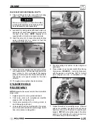
5. To check the contact area of the seat on the valve
face, apply a thin coating of Prussian Blue
t
paste
to the valve seat. If using an interference angle
(46
°
) apply black permanent marker to the entire
valve face (A).
(A)
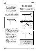
6. Insert valve into guide and tap valve lightly into
place a few times.
7. Remove valve and check where the Prussian
Blue
t
indicates seat contact on the valve face.
The valve seat should contact the middle of the
valve face or slightly above, and must be the
proper width.
G
If the indicated seat contact is at the
top edge of the valve face and
contacts the margin area(B) it is too
high on the valve face. Use the 30
°
cutter to lower the valve seat.
G
If too low, use the 60
°
cutter to raise
the seat.
When contact area is
centered on the valve face, measure
seat width.
G
If the seat is too wide or uneven, use
both top and bottom cutters to
narrow the seat.
G
If the seat is too narrow, widen using
the 45
°
cutter and re-check contact
point on the valve face and seat width
after each cut.
NOTE:
When using an interference angle, the seat
contact point on the valve will be very narrow, and is
a normal condition. Look for an even and continuous
contact point all the way around the valve face. (B)
(A)
(B)
Proper Seat Contact On Valve Face
Bottom - 60
°
Seat - 45
°
Top - 30
°
Seat
Width
Valve Seat Width:
Intake Std: .028
I
(.7 mm)
Limit: .055
I
(1
.
4 mm)
Exhaust Std: .039
I
(1.0 mm)
Limit: .071
I
(1.8 mm)
Содержание 600 Dragon SP
Страница 1: ...2004 SPORTSMAN 600 700 SERVICE MANUAL PN 9918803 ...
Страница 138: ...BODY STEERING SUSPENSION 5 16 NOTES ...
Страница 210: ...FINAL DRIVE 7 38 NOTES ...
Страница 293: ...ELECTRICAL 10 43 WIRING DIAGRAM HAND AND THUMB WARMERS WINCH HUNTER EDITION ...
Страница 294: ...ELECTRICAL 10 44 NOTES ...
Страница 295: ...ELECTRICAL WIRING DIAGRAM EARLY 2004 SPORTSMAN 600 700 BUILT BEFORE FEB 20 2003 Built Before February 20 2003 ...
Страница 297: ...ELECTRICAL WIRING DIAGRAM LATE 2004 SPORTSMAN 600 700 BUILT AFTER FEB 20 2003 Built After February 20 2003 ...
Страница 298: ...ELECTRICAL WIRING DIAGRAM LATE 2004 SPORTSMAN 600 700 BUILT AFTER FEB 20 2003 Built After February 20 2003 NOTES ...
Страница 299: ...ELECTRICAL WIRING DIAGRAM LATE 2004 SPORTSMAN 600 700 MODELS WITH FUEL GAUGE Models Equipped with Fuel Gauge ...
Страница 300: ...ELECTRICAL WIRING DIAGRAM LATE 2004 SPORTSMAN 600 700 MODELS WITH FUEL GAUGE NOTES ...
Страница 301: ...ELECTRICAL WIRING DIAGRAM 2004 SPORTSMAN 600 700 HUNTER EDT HAND WARM WINCH ...
Страница 307: ...Winch Switch Installation 10 34 Winch Wiring 10 35 Wiring Diagram Hand Thumb Warmer Winch 10 43 ...
Страница 308: ...PN 9918803 Printed in USA ...


