© 2019 Polara Engineering, Inc. Doc. 350-058-01 Rev. C-25059 12/4/2018 Page 2 of 2
www.polara.com
2. iPHCU3W
Note: Removing power from the pedestrian signal head during installation is
recommended for protection from electric shock.
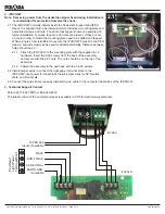
2.1 The iPHCU3W normally installs inside the Pedestrian Signal Head (PED
Head). It is supplied with a hardware kit which includes a mounting plate and
associated screws and nuts. The photo (next page) shows an example of a
typical installation. Typically, tapped ¼-20 holes are present. If they are not,
a hole (or holes) to match the mounting plate need to be drilled and tapped.
While a single screw is sufficient to secure the iPHCU3W bracket to the PED
Head, a second screw may be used for additional stability. Distance between
holes should be 9.3”.
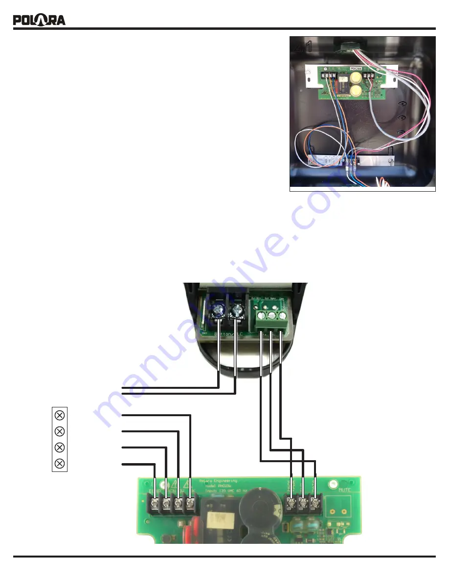
2.1.1 Attach the iPHCU3W to the mounting plate with the supplied 6-32
hardware. Insert the 6-32 screws from the back of the assembly
and secure with the 6-32 nuts. The nuts should be on the top of the
assembly.
2.1.2 Fasten the assembly to the ped head with the 1/4-20 screws.
2.2 Install jumper wires to connect the light power terminal block to the
iPHCU3W input power terminal block. Install jumper wires for AC Neutral,
Walk, and Don’t Walk.
2.3 Connect the wires from previously installed 3-wire cable to the output terminal block of the iPHCU3W.
3. Technical Support Contact
Polara @ 714-521-0900 or 888-340-4872
The latest version of the complete manual is available in PDF format at www.polara.com.
To PED Call
Inputs, if available
Ped Head Light Power Terminal
Block
WALK
DON’T WALK
iPHCU3W
iN3 PBS
AC NEUTRAL
EARTH GND,
if available
2.1