
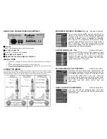


MAIN MIX AND ALT 3/4 CONTROLS
①
MAIN MIX FADERS
These faders control the LEFT and RIGHT MAIN MIX output levels.
(See
“
Ⓙ
MAIN OUTPUTS
” on page 9) Use these faders like a
system volume control.
②
ALT 3-4 FADERS
These faders control the ALT 3 and ALT 4 output levels. The left
fader controls ALT 3. The right fader controls ALT 4.
③
AUX 1 SEND
MON
Adjusts the output level of AUX 1 SEND output only. Typically used
to control the stage monitor speakers.
④
AUX 2 SEND
FX
Adjusts the output level of AUX 2 SEND only. Typically used to
control the signal level sent to external processor(s).
⑤ STEREO
AUX 1 RETURN
Adjusts the level of the incoming signal, which is mixed with the
LEFT/RIGHT bus.
⑥
STEREO AUX 1 RETURN
MON PRE
The STEREO AUX 1 RETURN signal is summed to mono, pre-
fader and sent to the AUX 1 bus. This allows the application of
effects to the stage monitors.
⑦
STEREO AUX 2 RETURN
Adjusts the level of the STEREO AUX 2 RETURN signal.
⑧
MAIN MIX / ALT 3 - 4
This push button assigns the STEREO AUX2 RETURN either to
the LEFT/RIGHT bus (MAIN MIX) or to the ALT 3 - 4 bus.
⑨
MAIN MIX PUSHBUTTON
When depressed, assigns the stereo MAIN MIX signal to the control room (CTRL R) and
headphone (PHONES) outputs.
⑩
ALT 3
– 4 PUSHBUTTON
When depressed, assigns the ALT 3
– 4 bus signal to the control room (CTRL R) and headphone
(PHONES) outputs.
⑪
TAPE PUSHBUTTON
When depressed, assigns the LEFT and RIGHT TAPE input signals to the control room (CTRL R)
and headphone (PHONES) outputs.
⑫
CTRL R & PHONES
Adjusts the level of the signal sent to the control room and headphone outputs.
⑬
TAPE TO MAIN PUSHBUTTON
Press to send the TAPE input directly to the LEFT/RIGHT bus (MAIN MIX). Typically used for
playback monitoring or adding pre-recorded elements to the mix..
⑭
LED VU METER
These LEDs indicate the signal level of the MAIN MIX. For best results, avoid operation above
0dB. Occasional flashing of the +5dB or even the +10dB may be allowable but operation with the
CLIP LEDs flashing must be avoided.
⑮
+48V
LED
Condenser microphones require an external power supply to operate. This blue LED lights
whenever the 48-volt microphone phantom power is on. The on/off switch for the phantom supply
is located on the rear panel of the console.
When the phantom supply is on, +48V is sent to
all four
of the microphone connectors.
You may use either dynamic or cond
enser microphones while the “phantom” power is
on.
Never use a balanced to unbalanced adapter when the phantom power is on!
⑯
POWER
LED
This red LED lights whenever the console is on. The AC power switch is located on the rear panel
of the console.
8
STEREO INPUT CONNECTIONS AND CONTROLS
①
MONO L
Balanced ¼” phone jack (TRS). LEFT or MONO line level input. NOTE:
When only the MONO
“L” input jack is used, the signal is sent to both left
and right channels (MONO).
①
R
Balanced ¼” phone jack (TRS). RIGHT line level input.
②
LEVEL
Use this pushbutton switch to set the circuit gain to 4dB (OUT) or
-10dB (IN).
③
HI EQ
Adjusts high frequencies up or down. Set to 0 (center detent) for no EQ.
④
MID EQ
Adjusts mid frequencies up or down. Set to 0 (center detent) for no EQ.
⑤
LOW EQ
Adjusts low frequencies up or down. Set to 0 (center detent) for no EQ.
⑥
MON
PRE
Adjusts the signal level sent to the AUX 1
bus.
“MON
PRE
” is before, or
pre FADER. This means FADER adjustments
will not
change the signal
level being sent to the AUX 1 bus.
⑦
FX
POST
FX is shorthand for Effects (reverb, echo, EQ). If you wish to route the
signal through an external device (effect) you would normally route it to
the AUX 2 bus. This control adjusts the signal level sent to the AUX 2
bus. “FX
POST
” is after, or post FADER. This means FADER adjustments
will
change the signal level being sent to the AUX 2 bus, allowing the
level of the external effect to “follow” the FADER.
⑧
BAL
Adjusts the relative signal level (BALANCE) sent to the LEFT/RIGHT
bus.
⑨
5/6
MUTE
ALT
3/4
PUSHBUTTON
The channel output normally goes to the LEFT/RIGHT bus. When “5/6
MUTE
ALT
3/4“
is depressed the signal is re-directed to the ALT 3 & 4
bus, which has the effect of muting the main output and making it
available for headphone monitoring.
MUTE
LED
This yellow LED lights whenever the 5/6 MUTE
ALT
3/4
⑨
is depressed.
⑪
PEAK
LED
This red LED lights when the input signal is too high. Lower source level when this
occurs.
⑫
FADER
Use only to “fade” the channel in or out during the performance. This is not a volume control.
5
Содержание MX1204
Страница 6: ...Podium Pro Audio MX1204 BLOCK DIAGRAM 6 7...


