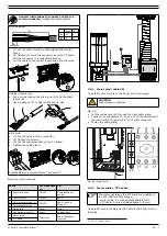
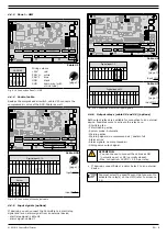
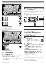
background image

010219/0 ControlPro/Diluter 

NL - 14

VOORWOORD

Gebruik van deze handleiding

Deze handleiding is bedoeld als naslagwerk waarmee 

professionele, geschoolde en daartoe bevoegde gebruikers het 

aan de voorzijde van dit document vermelde product op veilige 

wijze kunnen installeren, gebruiken, onderhouden en 

repareren.

Pictogrammen en symbolen

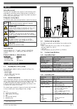
In deze handleiding worden de volgende pictogrammen en 

symbolen gebruikt:

TIP

Suggesties en adviezen om de betreffende taken of 

handelingen gemakkelijker te kunnen uitvoeren.

LET OP!

Een opmerking met aanvullende informatie voor de 

gebruiker. Een opmerking maakt de gebruiker attent 

op mogelijke problemen. 

VOORZICHTIG

Procedures die -wanneer ze niet met de nodige 

voorzichtigheid worden uitgevoerd- schade aan het 

product, de omgeving of het milieu tot gevolg 

kunnen hebben. 

WAARSCHUWING

Procedures die -wanneer ze niet met de nodige 

voorzichtigheid worden uitgevoerd- ernstige schade 

aan het product of lichamelijk letsel tot gevolg 

kunnen hebben.

VOORZICHTIG

Gevaar voor elektrische spanning.

Tekstaanduidingen

Tekst aangegeven met een “-” (koppelteken) betreft een 

opsomming. 

Tekst aangegeven met een “•” (bulletpoint) beschrijft de te 

verrichten stappen.  

Productaanduidingen/-afkortingen

Producttype: 

Is gelijk aan:


- ControlPro/Panel  

Panel


- ControlPro/HMI  

HMI

1


- SCS-Diluter PRO  

SCS-Diluter

INLEIDING

1.1 

Identificatie van het product

De identificatieplaatjes bevatten o.a. de volgende gegevens:


- productnaam


- serienummer


- aansluitspanning en frequentie


- vermogen

1.2 

Algemene beschrijving

ControlPro/Diluter van Plymovent is een intelligent 

bedieningspaneel met een geïntegreerde frequentieregelaar en 

een aparte HMI, dat wordt geleverd inclusief de benodigde 

aansluitkabels. Dit systeem regelt de besturing van de 

ventilator en de persluchtkleppen van het aangesloten 

filtersysteem SCS-Diluter.

Het bedieningspaneel bevat een frequentieregelaar en is 

verdeeld in twee compartimenten (hoogspanning resp. 

laagspanning).

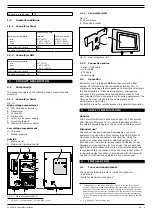
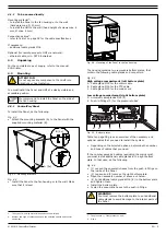
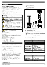
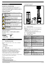
1.  Human Machine Interface

Fig. 1.2

A  Aansluitdoos CB-SCS

B  Filtersysteem SCS-Diluter

C  HMI

D  Panel [bedieningspaneel]

E  Ventilator

Fig. 1.2 

B C

D

E

A

A

B
C

D

E

F

G

H

SCS-D ControlPro/Diluter

1.3 

Opties en accessoires

De volgende producten zijn als optie en/of accessoire 

verkrijgbaar:


- Panel 

 HMI kabel 30 of 60 m (in plaats van standaardlengte 

15 m)


- LightTower | Signaalzuil


- externe pressure sensors (PT-1000 of PT-2500)

1.4 

Technische specificaties

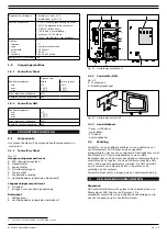
1.4.1  ControlPro/Panel

Afmetingen

zie Fig. I op pagina 36

Gewicht

55 kg

Materiaal (behuizing)

plaatwerk

Beschermingsklasse

IP 54

Ingangsspanning

400V3ph/50Hz | 480V/3ph/60Hz | 

600V/3ph/60Hz

Interne bedrijfsspanning

24 VDC (besturing) 

115V / 230V (koelventilator)

Opgenomen vermogen

max. 7,5 kW

Interne druksensors

2x geïntegreerde druksensor (voor 

filterdruk en ventilatordruk)

Keurmerken & certificaten

400V: CE
480V / 600V: cULus (UL 508A)

1.4.2  ControlPro/HMI

Afmetingen

255 x 165 x 125 mm 

Gewicht

900 g

Materiaal (behuizing)


- ontvlambaarheids-

klasse

PC/ABS


- standaard UL94 V-0

Bedrijfsspanning

24 VDC (+/- 15%)

Содержание CONTROLPRO/DILUTER

Страница 1: ...ent com EN Control panel with separate HMI NL Besturingskast met aparte HMI PL Panel sterowania z osobnym interfejsem HMI EN Installation manual NL Installatiehandleiding PL Instrukcja montażu CONTROLPRO DILUTER ...

Страница 2: ...jnen bekende constructies materiaaleigenschappen en werkmethoden zodat wijzingen worden voorbehouden Om deze reden dienen de gegeven instructies slechts als richtlijn voor het installeren gebruiken onderhouden en repareren van het op de voorzijde van dit document vermelde product Deze handleiding is geldig voor het product in de standaard uitvoering De fabrikant kan derhalve niet aansprakelijk wor...

Страница 3: ...allation 4 4 Installatie 16 4 Instalacja 27 5 Commissioning 10 5 Ingebruikname 21 5 Uruchomienie 32 6 Use 11 6 Gebruik 22 6 Użytkowanie 33 7 Maintenance 12 7 Onderhoud 23 7 Obsługa 34 8 Troubleshooting 12 8 Verhelpen van storingen 23 8 Rozwiązywanie problemów 34 9 Spare parts 13 9 Reserveonderdelen 24 9 Części zamienne 35 10 Electrical diagram 13 10 Elektrisch schema 24 10 Schemat elektryczny 35 1...

Страница 4: ... including the required connection cables This system controls the fan and the compressed air valves of the connected filter system SCS Diluter The control panel contains a frequency inverter and is divided in two compartments high voltage and low voltage Fig 1 2 A Junction box CB SCS B Filter system SCS Diluter C HMI D Panel control panel E Extraction fan 1 Human Machine Interface Fig 1 2 B C D E...

Страница 5: ...MI you can program all desired parameters The HMI gives a clear insight into the system status and performance at all times ControlPro allows for remote access via a network connection 3 SAFETY INSTRUCTIONS General The ControlPro Diluter is delivered as part of a filter system SCS Diluter of Plymovent The safety instructions written in the related manuals apply to the ControlPro Diluter as well In...

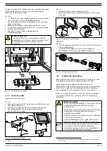
Страница 6: ...ons and control equipment Fig 4 4 Mounting of the Panel to the fan housing The housing contains two removable bottom plates that contain the following cable glands and connectors Fig 4 3 High voltage compartment left bottom plate A Cable gland M25 for the motor cable B Cable gland M16 for the PTC cable C Cable gland M25 for the mains cord Low voltage compartment right bottom plate D Universal cabl...

Страница 7: ...e electric connection of all necessary and optional components to the Panel Depending on the specific configuration of the filter system some of the connections on the PC board inside the Panel remain unused The PC board contains detachable screw terminal blocks connectors Table I on page 38 gives an overview of the necessary and optional cables9 that you need to install the system WARNING Shorten...

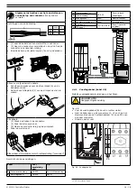
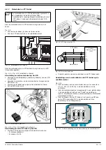
Страница 8: ... For connection of To A Pneumatic hose CB SCS Compressed air supply B Control cable CB SCS Panel C Filter pressure tube CB SCS Panel push in fittings D Filter pressure tube E Mains cord Panel Mains F Fan pressure tube Panel Vertical duct G Motor cable Fan motor Panel frequency inverter H PTC cable A B C D E F G H 4 4 1 Mains cord cable 5 To install the mains cord to the Panel do the following CAUT...

Страница 9: ...W 98 53 13 53 13 99 PE X3 9 10 X3 11 12 X3 13 14 X3 1 2 X3 3 4 X3 5 6 X3 7 8 X1 5 6 solenoid X1 7 8 solenoid X1 3 4 compressed air X1 1 2 P filter PTC cable PMD ca VFD VFD Mains cable Pressure tran PT 100 Main switch Mains motor cable PMD cable System control panel SCP 5 PE 6 7 PE 8 Solenoid ca X3 9 10 X3 11 12 X3 13 14 X3 1 2 X3 3 4 X3 5 6 X3 7 8 VFD 53 12 X 1 2 P P PTC cable Danfoss frequency in...

Страница 10: ...sensor Digital input 1 5 RS485 VFD CAN Slave CAN HMI Digital input 6 12 Filter Pressure sensor Analog output Light tower Power Relays Cable 6 Digital input 1 5 1 24V 2 IN 1 3 24V 4 IN 2 5 24V 6 IN 3 7 24V 8 IN 4 9 24V 10 IN 5 11 COM1 12 GND Digital inpu 1 24V 2 IN 1 3 24V 4 IN 2 5 24V 6 IN 3 7 Digital input 6 12 1 24V 2 IN 6 3 24V 4 IN 7 5 24V 6 IN 8 7 24V 8 IN 9 9 24V 10 IN 10 11 24V 12 IN 11 13 ...

Страница 11: ...tor LED s es Dustbin sensor Fan Pressure sensor Digital input 1 5 RS485 VFD CAN Slave CAN HMI Digital input 6 12 Filter Pressure sensor Analog output Light tower RS 232 for service only Filter pressure internal sensor Fan pressure internal sensor s 5 OUT 2 6 GND Indicator LED s 1 24V 2 PWR 3 RUN 4 ALA 5 WRN 6 24V 7 BUZ Dustbin sensor 1 24V 2 IN 1 3 GND 4 SHD Fan Pressure sensor 1 24V 2 IN 2 3 GND ...

Страница 12: ... to exit the screen The new values will be saved Fig 5 1 PID setpoint 6 USE 6 1 Control panel Panel The control panel contains the following controls and indicators 13 All nozzles 100 open Outside Fig 6 1 also refer to Fig II on page 36 A White LED POWER ON LED off system is off LED blinking system is starting up LED on system is ready B Green LED FAN RUNNING LED off fan is off LED blinking fan is...

Страница 13: ... every X months X 3 X 12 For maintenance of the connected filter system fan and other components refer to the corresponding manuals 8 TROUBLESHOOTING If the system does not function correctly consult the checklist below to see if you can remedy the error yourself Should this not be possible contact your supplier WARNING If applicable put the Panel in the Service Mode before you do the activities a...

Страница 14: ...eclaration of Conformity for machinery We Plymovent Manufacturing B V Koraalstraat 9 1812 RK Alkmaar the Netherlands herewith declare on our own responsibility that the product ControlPro Diluter which this declaration refers to is in accordance with the conditions of the following Directives EMC 2014 30 EU EMC Directive LVD 2014 35 EU Low Voltage Directive Harmonised Standards EN IEC 60204 1 2006...

Страница 15: ...vatten o a de volgende gegevens productnaam serienummer aansluitspanning en frequentie vermogen 1 2 Algemene beschrijving ControlPro Diluter van Plymovent is een intelligent bedieningspaneel met een geïntegreerde frequentieregelaar en een aparte HMI dat wordt geleverd inclusief de benodigde aansluitkabels Dit systeem regelt de besturing van de ventilator en de persluchtkleppen van het aangesloten ...

Страница 16: ...derdelen binnenkant Laagspanningscompartiment H Printplaat I Knoppen voor handmatige bediening Buitenkant J Statuspaneel K Hoofdschakelaar onderdelen buitenkant 2 CE 400V circuit breakers UL 480 600V fuses Fig 2 1 A B G I F D C H J K E Hoofdcomponenten Panel 2 1 2 ControlPro HMI Fig 2 2 A Touchscreen B Bevestigingsbeugel Fig 2 2 A B Hoofdcomponenten HMI 2 1 3 Aansluitkabels Panel HMI kabel motorka...

Страница 17: ...eren om het Panel aan de zijkant van de ventilatorbehuizing te monteren 4 3 1 ControlPro Panel Installeer het Panel als volgt Fig 4 3 Monteer de bevestigingsbeugels A aan het Panel met het meegeleverde montagemateriaal B 3 Gebruik volgens bestemming zoals vastgelegd in de EN ISO 12100 1 is het gebruik waarvoor het technisch product volgens de opgave van de fabrikant inclusief diens aanwijzingen in...

Страница 18: ...I kabel Optioneel Fig 4 7 Sluit de meegeleverde ethernet veld connector B aan op de ethernetkabel A Verwijder de blinddop zie Fig 4 6D en steek de ethernetkabel in de overeenkomstige LAN poort Fig 4 7 A B Ethernet veld connector 4 4 Elektrische aansluiting Deze paragraaf beschrijft de elektrische aansluiting van alle benodigde en optionele componenten aan het Panel Afhankelijk van de specifieke co...

Страница 19: ...rintplaat Draai de wartel vast 2 1 5 3 4 Afneembaar klemmenblok met schroefaansluiting connector Overzicht van de aansluitingen Kabel Voor aansluiting van Op A Pneumatische slang CB SCS Persluchtaansluiting B Besturingskabel CB SCS Panel C Filterdrukslang CB SCS Panel insteek koppelingen D Filterdrukslang E Voedingskabel Panel Elektriciteitsnet F Ventilatordrukslang Panel Vertikale buis G Motorkab...

Страница 20: ...C kabel op de VFD Fig 4 12 Control box CB PMD System control panel SCP M 3 Ø L1 L2 L3 13 33 U 96 V 97 W 98 53 13 53 13 99 PE X3 9 10 X3 11 12 X3 13 14 X3 1 2 X3 3 4 X3 5 6 X3 7 8 X1 5 6 solenoid X1 7 8 solenoid X1 3 4 compressed air X1 1 2 P filter PTC cable PMD ca VFD VFD Mains cable Pressure tran PT 100 Main switch Mains motor cable PMD cable System control panel SCP 5 PE 6 7 PE 8 Solenoid ca X3...

Страница 21: ...VFD CAN Slave CAN HMI Digital input 6 12 Filter Pressure sensor Analog output Light tower Power Relays Kabel 6 Digital input 1 5 1 24V 2 IN 1 3 24V 4 IN 2 5 24V 6 IN 3 7 24V 8 IN 4 9 24V 10 IN 5 11 COM1 12 GND Digital inpu 1 24V 2 IN 1 3 24V 4 IN 2 5 24V 6 IN 3 7 Digital input 6 12 1 24V 2 IN 6 3 24V 4 IN 7 5 24V 6 IN 8 7 24V 8 IN 9 9 24V 10 IN 10 11 24V 12 IN 11 13 24V 14 IN 12 15 COM2 16 GND Dig...

Страница 22: ...gital input 1 5 RS485 VFD CAN Slave CAN HMI Digital input 6 12 Filter Pressure sensor Analog output Light tower RS 232 for service only Filter pressure internal sensor Fan pressure internal sensor s 5 OUT 2 6 GND Indicator LED s 1 24V 2 PWR 3 RUN 4 ALA 5 WRN 6 24V 7 BUZ Dustbin sensor 1 24V 2 IN 1 3 GND 4 SHD Fan Pressure sensor 1 24V 2 IN 2 3 GND 4 SHD Analog output 1 OUT 2 GND 3 SHD Digital inpu...

Страница 23: ...zijn nu bewaard Fig 5 1 PID setpoint 6 GEBRUIK 6 1 Bedieningspaneel Panel Het bedieningspaneel van het Panel bevat de volgende bedieningsorganen en controlelampen 13 Alle nozzles 100 open Buitenkant Fig 6 1 zie ook Fig II op pagina 36 A Witte LED BEDRIJFSGEREED LED uit het systeem staat uit LED knippert het systeem start op LED brandt het systeem is bedrijfsgereed B Groene LED VENTILATOR DRAAIT LE...

Страница 24: ...riaal op de filterpatronen te behouden Onderdeel Actie Frequentie elke X maanden X 3 X 12 Panel Reinig de buitenkant met een niet agressief schoonmaakmiddel X Controleer of de wartels goed zijn aangedraaid X Controleer of alle afneembare klemmenblokken op de printplaat goed zijn aangesloten X HMI Reinig met een niet agressief schoonmaakmiddel X Controleer of the HMI kabel is aangesloten X Controle...

Страница 25: ...00060 Zoemer 9 2 ControlPro HMI Zie exploded view Fig IV op pagina 36 Artikelnr Omschrijving 0000112777 ControlPro HMI compleet 0000113560 Stofkap voor ControlPro HMI 10 ELEKTRISCH SCHEMA Zie het separaat bijgevoegde elektrisch schema 11 AFDANKEN Voer het product na het einde van de levensduur af conform de lokaal geldende voorschriften en of richtlijnen CE VERKLARING EG verklaring van overeenstem...

Страница 26: ...trolPro Diluter firmy Plymovent to inteligentny panel sterujący ze zintegrowanym przetwornikiem częstotliwości i osobnym interfejsem HMI który jest dostarczany wraz z wymaganymi kablami połączeniowymi System steruje wentylatorem i zaworami sprężonego powietrza podłączonego systemu filtrów SCS Diluter Sterownik zawiera przetwornicę częstotliwości i jest podzielony na dwa przedziały wysokie i niskie...

Страница 27: ...ącznik główny części wewnętrzne Przedział niskiego napięcia H Płytka PC I Sterowanie ręczne Zewnętrzne J Panel stanu K Wyłącznik główny części zewnętrzne 2 CE 400V wyłączniki obwodów UL 480 600V bezpieczniki Rys 2 1 A B G I F D C H J K E Panel głównych komponentów 2 1 2 ControlPro HMI Rys 2 2 A Ekran dotykowy B Uchwyt montażowy Rys 2 2 A B Główne komponenty HMI 2 1 3 Kable połączeniowe Panel Kabel...

Страница 28: ...ontrolPro Panel Aby zainstalować sterownik wykonaj następujące czynności Rys 4 3 Przymocuj wsporniki montażowe A do sterownika za pomocą dostarczonych materiałów montażowych B 3 Zastosowanie jak opisano w EN ISO 12100 1 jest to użycie do którego wyrób techniczny jest dostosowany w sposób określony przez producenta łącznie ze wskazówkami określonymi w broszurze sprzedaży W razie wątpliwości co do w...

Страница 29: ...Śruba blokująca i kabel interfejsu HMI Opcjonalnie Rys 4 7 Podłącz dostarczone złącze polowe Ethernet B do kabla ethernetowego A Zdejmij osłonę przeciwpyłową patrz Rys 4 6D i umieść przewód ethernetowy w odpowiednim porcie LAN Rys 4 7 A B Złącze pola Ethernet 4 4 Podłączenie elektryczne W niniejszym rozdziale opisano podłączenie elektryczne wszystkich niezbędnych i opcjonalnych komponentów do pane...

Страница 30: ...Wąż pneumatyczny CB SCS Zasilanie sprężonym powietrzem B Kabel sterowniczy CB SCS Panel C Rurka ciśnienia filtra CB SCS Panel złączki wciskane D Rurka ciśnienia filtra E Przewód zasilający Panel Sieć zasilająca F Rurka ciśnienia filtra Panel Kanał pionowy G Kabel silnika Silnik wentylatora Sterownik przemiennik częstotliwości H Kabel PTC B C D E A A B C D E F G H 4 4 1 Przewód zasilający kabel 5 A...

Страница 31: ...L1 L2 L3 13 33 U 96 V 97 W 98 53 13 53 13 99 PE X3 9 10 X3 11 12 X3 13 14 X3 1 2 X3 3 4 X3 5 6 X3 7 8 X1 5 6 solenoid X1 7 8 solenoid X1 3 4 compressed air X1 1 2 P filter PTC cable PMD ca VFD VFD Mains cable Pressure tran PT 100 Main switch Mains motor cable PMD cable System control panel SCP 5 PE 6 7 PE 8 Solenoid ca X3 9 10 X3 11 12 X3 13 14 X3 1 2 X3 3 4 X3 5 6 X3 7 8 VFD 53 12 X 1 2 P P PTC c...

Страница 32: ...ower Power Relays Kabel 6 Digital input 1 5 1 24V 2 IN 1 3 24V 4 IN 2 5 24V 6 IN 3 7 24V 8 IN 4 9 24V 10 IN 5 11 COM1 12 GND Digital inpu 1 24V 2 IN 1 3 24V 4 IN 2 5 24V 6 IN 3 7 Digital input 6 12 1 24V 2 IN 6 3 24V 4 IN 7 5 24V 6 IN 8 7 24V 8 IN 9 9 24V 10 IN 10 11 24V 12 IN 11 13 24V 14 IN 12 15 COM2 16 GND Digital input 6 12 1 24V 2 IN 6 3 24V 4 IN 7 5 24V 6 IN 8 7 24V 8 IN 9 9 24V 10 IN 10 11...

Страница 33: ...ys Kabel 22 Indicator LED s es Dustbin sensor Fan Pressure sensor Digital input 1 5 RS485 VFD CAN Slave CAN HMI Digital input 6 12 Filter Pressure sensor Analog output Light tower RS 232 for service only Filter pressure internal sensor Fan pressure internal sensor s 5 OUT 2 6 GND Indicator LED s 1 24V 2 PWR 3 RUN 4 ALA 5 WRN 6 24V 7 BUZ Dustbin sensor 1 24V 2 IN 1 3 GND 4 SHD Fan Pressure sensor 1...

Страница 34: ...p wentylatora gdy pożądany przepływ powietrza zostanie osiągnięty Wybierz Koniec do opuszczenia ekranu Nowe wartości zostaną zapisane Rys 5 1 Ustawienia PID 12 Wszystkie dysze 100 otwarte 6 UŻYTKOWANIE 6 1 Panel sterowania Panel Panel sterowania zawiera następujące elementy sterujące i diody sygnalizacyjne Zewnętrzne Rys 6 1 zobacz również Fig II na stronie 36 A Biała dioda LED POWER ON ZASILANIE ...

Страница 35: ...oki wstępnej na wkładach filtra Komponenty Czynność Częstotliwość każdego X miesiąca X 3 X 12 HMI Wyczyść z zewnątrz przy użyciu łagodnych detergentów X Upewnij się że kabel interfejsu HMI jest podłączony X Sprawdź aktualizacje oprogramowania układowego patrz instrukcja użytkownika online X Informacje na temat konserwacji podłączonego systemu filtrów wentylatora i innych komponentów można znaleźć ...

Страница 36: ...zator dźwiękowy 9 2 ControlPro HMI Zobacz rysunek Fig IV na stronie 36 Nr artykułu Opis 0000112777 ControlPro HMI komplet Nr artykułu Opis 0000113560 Osłona przeciwpyłowa dla ControlPro HMI 10 SCHEMAT ELEKTRYCZNY Zapoznaj się z oddzielnie dostarczonym schematem elektrycznym 11 UTYLIZACJA Po zakończeniu użytkowania produktu usuń go zgodnie z prawem DEKLARACJA CE Deklaracja zgodności CE dla maszyn M...

Страница 37: ... SOUS TENSION ENCENDIDO FAN RUNNING VENTILATOR DRAAIT VENTILATOR EIN MARCHEVENTILATEUR VENTILADOR EN FUNCIONAMIENTO 0000112513 A WARNING WAARSCHUWING WARNUNG ATTENTION ATENCIÓN ALARM ALARM ALARM ALARME ALARMA Fig III ControlPro Panel 0324000310 0324000300 0000113558 0324000320 0000103139 0000113559 0360000060 0040900180 Fig IV ControlPro HMI 0000113560 0000112777 ...

Страница 38: ... throw at VT qV air volume per nozzle NL VT eindsnelheid van de worp Vf snelheid bij uitblaas van de nozzle LT worp bij VT qV debiet per nozzle PL VT końcowa prędkość rzutu Vf prędkość na wylocie dyszy LT wyrzut przy VT qV objętość powietrza na dyszę Fig VI Horizontal throw per nozzle Af waarden m2 Correctie geluidsniveau Hoekinstelling α α tussen 0 en 25 α tussen 25 en 30 Technische wijzigingen v...

Страница 39: ...wór SCS przełącznik sprężonego powietrza 22 Signaalzuil Świetlna wieża sygnalizacyjna Table II Digital inputs Input EN Input NL Ingang PL Wejście High Low Hoog Laag Wysoki Niski IN 5 External signal fan start stop Extern signaal ventilator start stop Zewnętrzny sygnał start stop wentylatora start stop start stop start stop IN 6 Fire alarm Brandmelding Alarm pożarowy normal alarm normaal alarm norm...

Страница 40: ...www plymovent com 010219 0 ControlPro Diluter ...

Отзывы: