background image

TECHNICAL MANUAL BM 15 

T08099

28

4

2

3

1

5

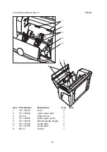
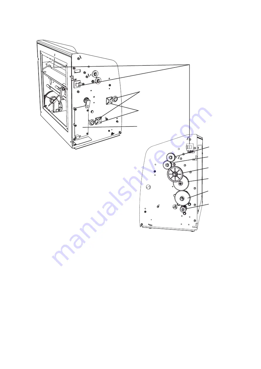
Item   Part number 

Description 

Q’ty 

Note

60633-UL Cable 

clamp 

3

80513 Grommet 

2

80889-UL Cable 

hanger 

2

151101 

Printed circuit board 

1

151107 

Upper fold roller gear  

Incl. one-way clutch

151108 

Lower fold roller gear 

Incl. one-way clutch 

107-100517 Gear 

wheel 

1

107-101792 Gear 

wheel 

1

151109 

Gear wheel assy 

Incl. plastic bushing

107-100520 Gear 


1

1.
2.
3.
4.
5.
6.
7.
8.
9.
10.

6

7

8

9

10

Содержание BM 15

Страница 1: ...A BOOKLET MAKER BM 15 Operator Manual 11 October 2006 Part no 107 102306 Doc no T10162 ...

Страница 2: ...B ...

Страница 3: ...C ...

Страница 4: ...D ...

Страница 5: ...E ...

Страница 6: ...F ...

Страница 7: ...G H I ...

Страница 8: ...H ...

Страница 9: ...I J ...

Страница 10: ...J ...

Страница 11: ...BOOKLET MAKER BM 15 TECHNICAL MANUAL SERVICE MANUAL PARTS LIST 9 October 2006 ...

Страница 12: ......

Страница 13: ...COVER 5 REP 2 2 FRONT COVER 6 REP 2 3 REAR COVER 7 REP 2 4 STAPLER MODULE 8 REP 2 5 STAPLER HEAD 11 REP 2 6 ANVILS 12 REP 2 7 FOLD KNIFE 14 REP 2 8 FOLD ROLLERS 16 REP 2 9 MOTOR 17 REP 2 10 SOLENOID 18 REP 2 11 START SENSOR 20 REP 2 12 INTERLOCK SWITCH 21 REP 2 13 PRINTED CIRCUIT BOARD 23 REP 2 14 BOOKLET QUALITY 24 3 PARTS LIST 27 ...

Страница 14: ...TECHNICAL MANUAL BM 15 T08099 4 1 DIRECTION CONVENTIONS The following terminology is used throughout this manual Front side Rear side Left side Right side ...

Страница 15: ... Front Cover Remove the screws A Remove the screws B Remove the cover Right Cover Removal of the Right Cover is performed the same way as removal of the Left Cover To completely remove the Right Cover slide out the panel according to arrow C and remove the cover 1 2 3 4 Replacement Reverse the removal procedure 1 A C B ...

Страница 16: ...99 6 REP 2 2 FRONT COVER Removal Remove the Left Cover according to REP 2 1 Open the Front Cover Remove the screw A and the lift cord Remove the screw B Lift off the cover 1 2 3 4 5 Replacement Reverse the removal procedure 1 A B ...

Страница 17: ...T08099 TECHNICAL MANUAL BM 15 7 REP 2 3 REAR COVER Removal Remove the screws A Remove the cover 1 2 Replacement Reverse the removal procedure 1 A ...

Страница 18: ...ECHNICAL MANUAL BM 15 T08099 8 REP 2 4 STAPLER MODULE Tilting the module open Open the Front Cover Press down A the Stapler Module and pull it outwards B 1 2 Stapler Module Stapler Module tilted open A B ...

Страница 19: ...ccording to REP 2 14 1 1 C B A Removal Remove the Left and Right Cover according to REP 2 1 Remove the Front Cover according to REP 2 2 Tilt the Stapler Module open Lower the fold stop to the cutout A by turning the adjustment wheel B Remove the screws C one on each side Unhook the module To fully remove the Stapler Module disconnect the cable 1 2 3 4 5 6 7 ...

Страница 20: ...TECHNICAL MANUAL BM 15 T08099 10 ...

Страница 21: ... 4 Remove the screws A holding both the stapler heads B and the mounting plate C Remove the stapler heads and the mounting plate Disconnect the cable 1 2 3 4 Replacement Reverse the removal procedure Adjustment Check adjustment according to REP 2 6 Check the booklet quality according to REP 2 14 1 1 2 A B C ...

Страница 22: ... 15 T08099 12 REP 2 6 ANVILS Removal Remove the Rear Cover according to REP 2 3 Tilt the Stapler Module open according to REP 2 4 Remove the screws A Remove the anvil 1 2 3 4 Replacement Reverse the removal procedure 1 A ...

Страница 23: ...they are not adjust the position of the anvils vertically The legs of the staples should have the same length If they do not adjust the position of the anvils horizontally 1 2 View from the side View from above a b a b a b a b Correctly formed staple No adjust ments needed Staple deformed lengthwise Adjust vertically Staple deformed sidewise Adjust horizontally ...

Страница 24: ...to REP 2 3 Remove the Left and Right Cover according to REP 2 1 Remove screws A holding the bar one on each side Remove the bar B Loosen the screws C two on each side holding the knife guides D Unhook and remove the Fold Knife E Replacement Reverse the removal procedure 1 2 3 4 5 6 1 B C A D E ...

Страница 25: ...ife guides one on each side Remove the gear wheel G Manually turn one of the gear wheels to move the Fold Knife in position between the fold rollers WARNING Make sure not to get your fingers caught between moving gear wheels Tighten the screws F and replace the gear wheel G 1 2 3 4 F G ...

Страница 26: ... gear wheels two on the right side Note the position of the fold rollers and remove them NOTE The lower fold roller has one indent B on each side while the upper has two indents C on each side 1 2 3 4 Replacement Reverse the removal procedure NOTE Due to the one way clutches in the gear wheels make sure to replace the gear wheels so that the fold rollers freewheel as shown in the picture 1 A B C ...

Страница 27: ...he Right Cover according to REP 2 1 Remove the gear wheel A Remove the retaining ring and the gear wheel B Remove the screws C Lift out the motor Note the position of the wires and disconnect the connectors see picture below 1 2 3 4 5 6 7 Replacement Reverse the removal procedure 1 A B C Red wire Black wire ...

Страница 28: ...er according to REP 2 3 Tilt the Stapler Module open according to REP 2 4 Remove the screws A Note the position of the wires and disconnect the solenoid connector see picture below Remove the solenoid B Replacement Reverse the removal procedure 1 2 3 4 5 1 A B Red wire Black wire ...

Страница 29: ...T08099 TECHNICAL MANUAL BM 15 19 Adjustment Push down the upper paper stop C and check that it reaches the base Move the solenoid to adjust 1 2 C ...

Страница 30: ...could be accessed by opening or removing the Front Cover according to REP 2 2 For best accessibility remove the Stapler Module according to REP 2 4 Remove the screw A through the hole in the upper paper guide Remove the sensor B 1 2 Replacement Reverse the removal procedure 1 A B ...

Страница 31: ...s see picture above and disconnect the connec tors from the switch Remove the screws A Remove the interlock switch 1 2 3 4 5 Replacement Reverse the removal procedure Adjustment Check that the switch activates when the Front Cover is properly closed and so it deactivates when the upper part of the Front Cover is pulled upwards Move the switch to adjust 1 1 2 A White wire Black wire ...

Страница 32: ...TECHNICAL MANUAL BM 15 T08099 22 ...

Страница 33: ...the Rear Cover according to REP 2 3 Remove the Left Cover according to REP 2 1 Remove the screws A Note the position of the wires see picture below and disconnect the connectors Remove the printed circuit board 1 2 3 4 5 Replacement Reverse the removal procedure 1 A P1 P7 P5 P4 P3 ...

Страница 34: ... Run a few A3 sets Check that the staples are positioned in the centre of the set figure 1 If not go to step 3 1 2 A B Remove the Left and Right Cover according to REP 2 1 Tilt the Stapler Module out according to REP 2 4 Loosen screws A one on each side Adjust the height of the stapling module by rotating the screws B Tighten the screws A Repeat Adjustment 1 until the staples are positioned in the...

Страница 35: ...ts Check that the set is folded in the centre of the set figure 2 If not go to step 3 1 2 Open the Front Cover Adjust the height of the fold stop A by turning the adjustment wheel B Repeat Adjustment 2 until the fold is in the centre of the set 3 4 5 A B Figure 2 ...

Страница 36: ...t the fold is parallel to the edge of the set figure 3 If not go to step 3 1 2 Remove the Rear Cover according to REP 2 3 Loosen the screws A Adjust by skewing the upper guide block B Tighten screws A Repeat Adjustment 3 until the fold is parallel to the edge of the set 3 4 5 6 7 A B ...

Страница 37: ...5 27 3 PARTS LIST Item Part number Description Q ty Note 107 100509 43UL Left cover 1 151103 Panel assy 1 151102 Front cover assy 1 107 100510 43UL Right cover 1 107 101448 26 Rear cover 1 107 100706 Foot 4 1 2 3 4 5 6 1 3 4 2 5 6 ...

Страница 38: ...Grommet 2 80889 UL Cable hanger 2 151101 Printed circuit board 1 151107 Upper fold roller gear 1 Incl one way clutch 151108 Lower fold roller gear 1 Incl one way clutch 107 100517 Gear wheel 1 107 101792 Gear wheel 1 151109 Gear wheel assy 1 Incl plastic bushing 107 100520 Gear 1 1 2 3 4 5 6 7 8 9 10 6 7 8 9 10 ...

Страница 39: ...63 Extension spring 2 151105 Upper fold roller assy 1 Incl shaft washers spring wheels retaining rings 151104 Lower fold roller assy 1 Incl shaft washers spring wheels retaining rings 107 101499 Guide plate 1 151106 Upper paper path assy 1 55980 Lift cord 2 1 2 3 4 5 6 1 3 2 4 5 6 ...

Страница 40: ...scription Q ty Note 107 100572 Anvil 2 107 100638 Lower paper path 1 151110 Stapler head 2 107 100552 Upper paper guide 1 107 100553 Mounting plate stapler 1 107 101820 Guide plate 2 107 101819 Guide plate 1 96133 Sensor 1 1 2 3 4 5 6 7 8 1 3 2 4 5 6 7 8 ...

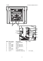
Страница 41: ...7 101170 Flanged bushing 2 56653 Spring 2 107 101006 Upper paper stop 1 107 101005 Lower paper stop 1 107 101068 Upper guide block 1 75947 Spring 2 107 101007 Rod 1 107 101714 Lower guide block 1 151111 Adjustment wheel assy 1 Incl inserts 1 2 3 4 5 6 7 8 9 2 1 6 7 5 8 9 3 4 ...

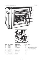
Страница 42: ... ty Note 151112 Paper stop arm 1 151113 Shaft 1 151114 Link arm assy 2 Incl clamp ring needle bearing cylindrical pin 107 100518 Support shaft 2 771008 Micro switch 1 107 101188 UL Solenoid 1 107 101862 Spring 1 107 101008 Bracket 1 1 2 3 4 5 6 7 8 1 7 6 5 4 3 2 8 ...

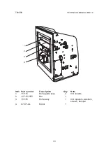
Страница 43: ...TECHNICAL MANUAL BM 15 33 Item Part number Description Q ty Note 151115 Knife guide assy 2 Incl inserts 107 101555 Bar 1 151116 Knife assy 1 Incl spacers washers screws damper 87271 UL Motor 1 1 2 3 4 3 2 1 4 ...

Отзывы: