


Quick Start Guide
2
C r e w C o m
C r e w C o m Q u i c k S t a r t G u i d e
A.
Place the CU on a flat, dry surface, or in a desired rack-mounted location (rack screws not included). Wherever it is placed, ensure that the air input
and output sections on the sides of the CU are not restricted.
B.
Connect the CU to a compatible power source using provided AC power cord, but
do not
turn on
power yet.
C.
Attach provided omni-directional antennas (2) to the RT and mount the RT in the center of desired
coverage area as high as possible and away from any obstructions (especially metal).
Note:
If using directional antennas (where legal), mount them on the edge of the coverage area and point antennas
across coverage area. Find more antenna positioning recommendations and detailed RT mounting procedures
on Pliant’s website and Online Help.
Note:
This document does not cover configuration nor use of a CrewCom Hub. For more information about Hubs and
other advanced CrewCom configuration possibilities, refer to the documentation provided on Pliant’s website
and Online Help.
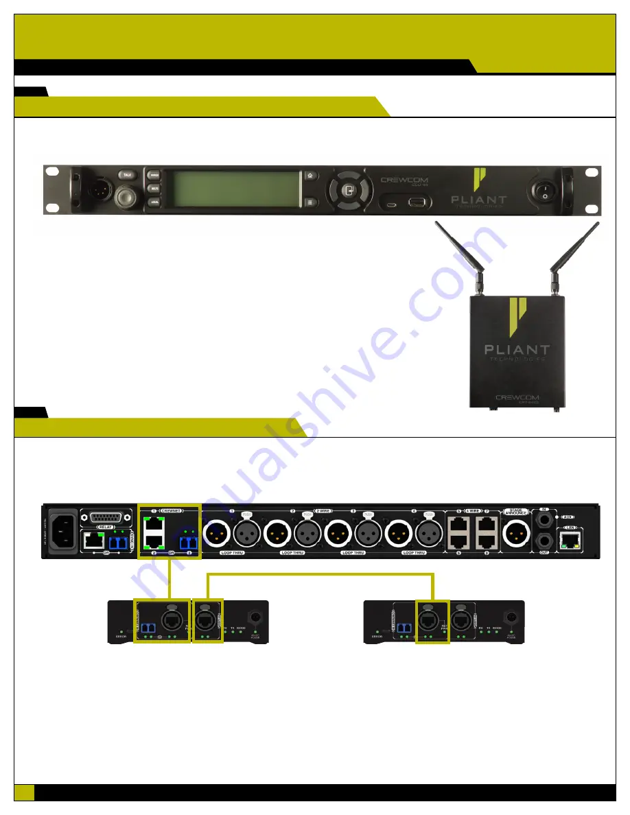
Control Unit (CCU-44)
Radio Transceiver (CRT-2400)
2
Position Control Unit (CU) and Radio Transceiver (RT).
IMPORTANT:
Device port connections must match your CCF’s system diagram in order to operate.
A.
Connect at least one RT to the CU via an available CrewNet
™
port.
B.
If you have additional RTs, connect via an available CrewNet port on a CU (or Hub if applicable), or by daisy-chaining to an existing RT.
CrewNet Port Types
RJ-45 Ports
- Use the supplied 15 ft. (4.6 m) Cat 5e cable, or your own Cat 5e (or greater) cable (up to 330 ft. (100 m) in length). Any CrewCom device connected to
CrewNet via a Cat 5e (or greater) cable will receive Power Over CrewNet (PoC) via the CrewNet port. In some situations, there may be too many connected devices or the
cable lengths may be too long for the PoC to adequately power all devices, and this will be indicated by the NET PWR LED lighting red. In this case, one or more additional
Pliant 48VDC power supplies must be used (PPS-48V-02 included with Hubs; sold separately with all other devices).
Fiber (Optical) Ports
- For a fiber CrewNet port, a Single Mode Fiber cable (duplex LC connector) will be required (up to 32,800 ft. (10,000 m) in length). Any CrewCom
device connected to CrewNet via fiber port must receive power via a Pliant 48VDC power supply (PPS-48V-02 included with Hubs; sold separately with all other devices).
CrewNet
Connection
2nd CrewNet Connection
Connection Ports on
back of Control Unit
(CCU-44)
Additional RT via CrewNet daisy-chain
Connection Ports on bottom of RT
3
Connect the RTs.


