


39
Copyright © 2011 Pleora Technologies Inc.
To configure a persistent IP address:
1. Connect to the iPORT SB-Pro IP engine. Click
GEV Device Control
in the
Parameters and
Controls
section.
2. In the
TransportLayerControl
category, set the
GevCurrentIPConfigurationPersistentIP
feature to
True
.
3. Set the
GevPersistentIPAddress
feature to a valid IP address in the
GevPersistentIPAddress
field.
4. Set the
GevPersistentSubnetMask
feature to a valid subnet mask address.
5. Optionally, enter a valid default gateway next to
GevPersistentDefaultGateway
.
6. Close the
GEV Device Control
dialog box.
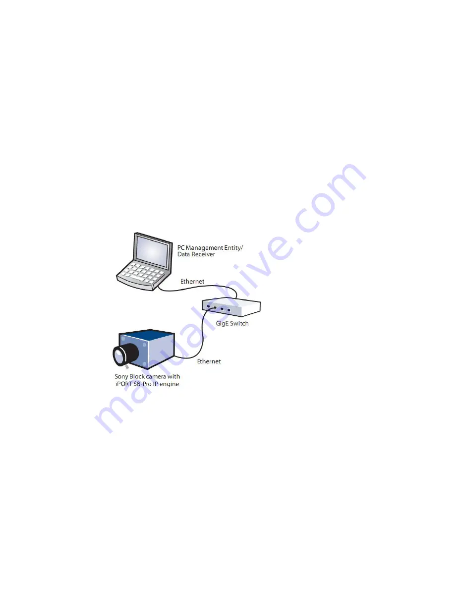
Unicast Network Configuration
You can set up the iPORT SB-Pro IP engine in a simple unicast network configuration. The IP engine
can be connected to a PC either directly, or through a GigE switch. The PC is configured as both a data
receiver and controller. The PC serves as a management entity for the IP engine. The figure below
illustrates the iPORT SB-Pro IP engine in a unicast network configuration.
Unicast Network Configuration: Figure 16.
Overview
For a unicast configuration, an integrated Sony
®
Block FCB-H11 with the iPORT SB-Pro IP engine is
connected to a GigE switch that sends a stream of video over Ethernet to the PC. Alternatively, the IP
engine can be connected directly to the PC.
System Requirements
You require the following components to set up a unicast network configuration:
•
Sony
®
Block FCB-H11 Camera with iPORT SB-Pro IP engine
•
6 - 12V power supply
•
Cat5e or Cat6 Ethernet cables (2)
•
GigE Switch (optional)
•
PC or Laptop with eBUS SDK, version 2.0.0 (or higher) installed
Содержание iPort SB-Pro
Страница 1: ...SB Pro IP Engine For Sony FCB H11 Block Cameras User Guide...
Страница 2: ......
Страница 3: ...High Performance Imaging Data and Video Over Ethernet...
Страница 13: ...13 Copyright 2011 Pleora Technologies Inc PCB Stack C Figure 3 PCB Stack D Figure 4...
Страница 15: ...15 Copyright 2011 Pleora Technologies Inc Daughter Card Layout A Figure 7 Daughter Card Layout B Figure 8...
Страница 18: ...18 Assembling the iPORT SB Pro IP Engine Copyright 2011 Pleora Technologies Inc Bracket Figure 13...
Страница 19: ...19 Copyright 2011 Pleora Technologies Inc 12 Pin GPIO and Power Connector A Figure 14...
Страница 32: ...32 Assembling the iPORT SB Pro IP Engine Copyright 2011 Pleora Technologies Inc...
Страница 50: ...50 iPORT SB Pro IP Engine Feature Settings Copyright 2011 Pleora Technologies Inc...
Страница 52: ...52 Status LEDs Copyright 2011 Pleora Technologies Inc...


