


from the start menu.
With the Serial Cable attached to the computer, and the mono plug
inserted into the jack on the side of the transmitter, hold the Right stick
Up - while simultaneously switching the transmitter from off to ON
The transmitter will now be in the NON TRANSMITTING mode and can
be used as an input device for the flight simulator.
In the FMS program click the menu "Controls" then click on " Analog
controls…" .
Select "Serial PIC Interface" and then click the button marked
"Resources". Then you will need to select the com port which the cable
is connected to. (Probably COM1)
For the Baud Rate Choose "19200" . Then Press OK
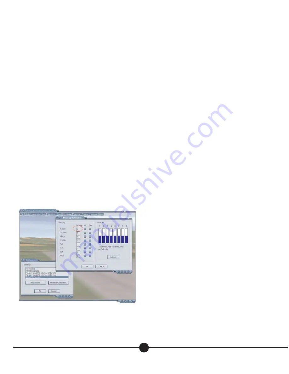
Then Click "Mapping/Calibration" then click "Calibrate" you should
now move both sticks in all directions to allow the software to adjust to
the range of motion available.
Rudder is set to 1 be default, but some models will require it to be set
to 3 for proper flight controls.
See FIg 9
You can see the blue bars moving up and down to confirm full range of
motion.
Two or three big circles with both sticks should be fine.
Click Ok.
And then click ok again.
The aircraft on screen should now start rolling ahead - You should now
be able to affect the aircraft by moving the control sticks.
To switch back to a transmitting mode hold the right stick to the right
and simultaneously switching the transmitter from off to ON.
T
ROUBLESHOOTING
We hope that you won’t have any problems with your Butterfly, but if
you do, check this Troubleshooting list first.
1. My Receiver played the startup tones through my actua-
tor at startup, but then it just plays the C-E tones over
and over - it keeps beeping.
• Check transmitter - Make sure the switch is all the way to the right
and the transmitter LED is glowing
• Is the transmitter in FMS mode? Switch the Tx off for a few sec-
onds and then startup with the Right joystick held to the right for 2
seconds - Let the stick go and you should be in normal rudder
elevator R/C mode again. Now remove the battery from the receiv-
er and start it up again. You should hear the arpeggio tones, and
then the C-E tones and then a few G tones to tell you what channel
you have just locked-on (synced) to.
• Change your Transmitter batteries for fresh ones and try again
• Check if your receiver still has it’s antennas - have they been bro-
ken off or cut? replace and try again or contact Plantraco
2. When I charge my LP30 cell on the built-in charger of
the transmitter, the LED goes out right away, but the cell
doesn’t seem to have much power anymore.- Or - It
seems to be taking forever to charge my LP30 cell.
• Replace the AA batteries in the transmitter- they are probably low and
we have to have greater than 4.4 Volts left in the 4 AA cells in
order to charge up the LP30 cell. A normal Charge will take about
60 minutes With fresh AA cells in the transmitter, you should be able
to get about 30 charges of your LP90 cell - you may get more, depend-
ing on how you use your cells, but eventually, the AA cells of the trans-
mitter will become depleted, so be mindful of the charger LED. It can
be a good idea to use a digital volt meter (these are often available for
less than $15.00 these days) to check your cell voltage once in a while.
3. I sync up fine, but the controls seem to be reversed or
something - when I give it elevator, I get rudder - it’s all
messed up
• You are in V-Tail mixing mode. Power off the transmitter for 5
seconds and restart the transmitter while holding the Right joystick
to the right for about 2 seconds and when you release it, you
should have normal control again.
4. I sync up fine, when the models is throttled up or is
shaken, the battery seems to lose it’s connection, and
the receiver starts up again, I can hear the tones.
• Try squeezing the Bahoma battery magnet terminals of the cell and
slide the battery around on the receivers magnets when you make
a connection - this will help to clear any debris that might be pre-
venting the Bahoma magnets from getting a good electrical con-
7
Fig. 9
Setup of the FMS Flight Sim. These are Screenshots of the
Mapping and Calibration and Control Screens


