Planet WGS-5225-8UP2SV Скачать руководство пользователя страница 7

7

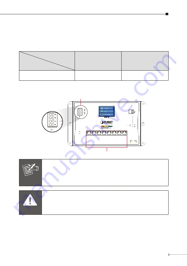
4. Wiring the Power Inputs

The Wall-mount Managed Switch features a strong dual power input system 
incorporated into customer’s automation network to enhance system reliability and 
uptime.

Power Input

Range

Model

PWR1

PWR2

WGS-5225-8UP2SV

DC 48-54V, 8A max

DC 48-54V, 8A max

Note:

 Maximum power requirements also rely on the real site application.

ACT

LNK

ACT

LNK

1G/2.5G
100

1000 LNK/ACT

10/100 LNK/ACT
bt PoE-in-Use

at PoE-in-Use

R.O.

Ring

PWR 2

PWR 1

SFP

9

10

PWR 1

V1

V1+

PWR 2

V2

V2+

3

4

2

1

7

8

6

5

WGS-5225-8UP2SV

Managed

Fiber

PoE++

SFP

9

10

Alarm

Smart LCD

DC Input Range

48-54V    , 8A max.

PoE++

Dual power input is required

for maximum PoE loading.

Max. Fault Alarm Loading: 24V, 1A

10/100/1000BASE-T 802.3bt PoE++ RJ45 Port

4-pin Spring Terminal Block

V1

V1+

V2

V2+

DC Input Range

48-54V    , 8A max.

Note

Dual power input is required for maximum PoE loading


Single power

 input: Max. 

360 watts

 PoE budget@52-54V DC


Dual power

 input: Max. 

720 watts

 PoE budget@52-54V DC

Caution

PWR1 and PWR2 must provide 

exactly same DC voltage

 for 

power load balance while operating with dual power input.

Содержание WGS-5225-8UP2SV

Страница 1: ...Industrial L2 8 Port 10 100 1000T 802 3bt PoE 2 Port 1G 2 5G SFP Wall mount Managed Switch with LCD Touch Screen WGS 5225 8UP2SV Quick Installation Guide...

Страница 2: ...er Inputs 7 4 1 Terminal Block Connector Pinout 8 4 2 Wiring Completed in Three Steps 8 4 3 Wiring the Alarm Contact 9 5 Web Login 10 5 1 Starting Web Management 10 5 2 Saving Configuration via the We...

Страница 3: ...ons unless specified the term Wall mount Managed Switch mentioned in this quick installation guide refers to the above model Open the box of the Wall mount Managed Switch and carefully unpack it The b...

Страница 4: ...t Connection Network cables Use network UTP cables with RJ45 connectors The above Workstations is installed with Web browser The above Workstations have been installed with SSH and telnet client soft...

Страница 5: ...tep 2 Hammer the four anchors into the four holes 1 2 Step 3 Then the four given screws are screwed into the anchors to finish the wall mount installation as shown below ACT LNK ACT LNK 1G 2 5G 100 10...

Страница 6: ...K ACT LNK 1G 2 5G 100 1000 LNK ACT 10 100 LNK ACT bt PoE in Use at PoE in Use R O Ring PWR 2 PWR 1 SFP 9 10 PWR 1 V1 V1 PWR 2 V2 V2 3 4 2 1 7 8 6 5 WGS 5225 8UP2SV Managed Fiber SFP 9 10 Alarm Smart L...

Страница 7: ...ing PWR 2 PWR 1 SFP 9 10 PWR 1 V1 V1 PWR 2 V2 V2 3 4 2 1 7 8 6 5 WGS 5225 8UP2SV Managed Fiber PoE SFP 9 10 Alarm Smart LCD DC Input Range 48 54V 8A max PoE Dual power input is required for maximum Po...

Страница 8: ...lade screwdriver pressed into the release hole and insert the wire into the terminal hole Step 3 Remove the flat blade screwdriver from the release hole After you connect the wires pull gently on the...

Страница 9: ...iver Note The wire gauge should be in the range from 12 to 16 AWG 4 3 Wiring the Alarm Contact The alarm contacts are in the middle of the terminal block connector as the picture shows below Inserting...

Страница 10: ...number between 1 and 254 except 100 and the default subnet mask is 255 255 255 0 PC Workstation with Web Browser 192 168 0 x Managed Switch RJ45 UTP Cable IP Address 192 168 0 100 Figure 5 1 IP Manag...

Страница 11: ...lets you access all the commands and statistics the Wall mount Managed Switch provides The Switch Menu always contains one or more buttons such as System Switching Routing QoS Security Ring and Maint...

Страница 12: ...figuration as a startup configuration the startup configuration file will be loaded automatically across a system reboot 1 Click the Save icon on the top Switch Menu bar 2 Press the Save Configuration...

Страница 13: ...ault IP address 192 168 0 100 Username admin Password admin Figure 6 1 Wall mount Managed Switch SSHv2 Login Screen The user can now enter commands to manage the Wall mount Managed Switch For a detail...

Страница 14: ...The screen displays the current IP address shown in Figure 6 2 Figure 6 2 IP Information Screen Configuration of the IP Address 3 At the prompt enter the following command and press Enter as shown in...

Страница 15: ...ation Command Screen If the IP is successfully configured the Wall mount Managed Switch will apply the new IP address setting immediately You can access the Web interface of the Wall mount Managed Swi...

Страница 16: ...the default IP address 192 168 0 100 or reset the login password to default value press the reset button on the front panel for about 5 seconds After the device is rebooted you can log in the Web int...

Страница 17: ...screen Figure 8 1 To wake the LCD touch screen The factory default LCD configurations are shown as follows Default LCD Enable Default Touch Screen Enable Default Backlight Timeout Enable Default Backl...

Страница 18: ...18 You can use the Web management interface and click LCD and then in the LCD Management change LCD configuration Please refer to the user s manual for more...

Страница 19: ...rt team PLANET online FAQs https www planet com tw en support faq Support team mail address support planet com tw WGS 5225 8UP2SV User s Manual https www planet com tw en support downloads method keyw...

Страница 20: ......

Отзывы: