– 1 –
– 2 –
– 3 –
– 4 –
KVM-210-08M/KVM-210-16M
Quick Installation Guide
17" 8/16-Port
Combo VGA LCD KVM Switch
1. Package Contents
Thank you for choosing PLANET KVM-210-08M/KVM-210-16M
LCD KVM Switch. The KVM Switch provides a useful function
that controls a computing infrastructure that combines multiple
computers with other peripherals.
Open the box of the KVM Switch and carefully unpack it. The
box should contain the following items:
z
LCD KVM Switch x 1
z
Quick Guide x 1
z
KVM Cable x 1
z
Power Adapter x 1
z
Power Cord x 1
z
Rack-mounting Kit x 1
z
Stand Kit x 1
z
M6 Screw x 12
Note
If there is any item missing or damaged, please
contact the seller immediately.
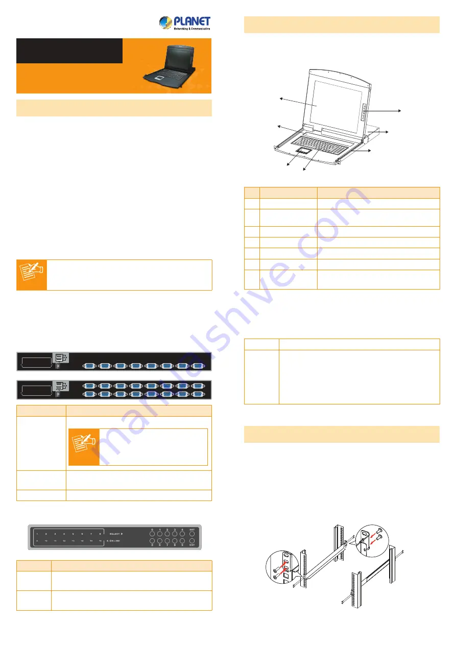
2. Physical Introduction
8/16-Port Combo KVM Switch
Control Platform
1
2
4
5
6
7
3
No. Component
Function Description
1 LCD
17" LCD screen
2 Port Select Panel
Switch the Port Number and display
the online port
3 Touchpad
Mouse Operation
4 Keyboard
Keyboard Operation
5 Slide Rail
Single Slide Rail
6 8-/16-port KVM
Modular KVM for 8/16 ports
7
LCD Panel OSD
Buttons
Controls Display Required Quality
Rear Panel
DC 12V
8
7
6
5
4
3
2
1
16
15
14
13
12
11
10
9
DC 12V
8
7
6
5
4
3
2
1
Interface
Description
Power Jack
The input power is 12V DC.
Note
Use the power adapter included
in the package; otherwise, it
may damage the unit and result
in danger.
USB Port
Plug external USB keyboard and mouse into
this port.
Computer Port Install the KVM cable connected to a PC here.
Port Select Panel
Interface
Description
Online
If a corresponding LED number is on, it means
the port is online. Otherwise, the port is off.
Select
The selected port number will display here in
segment display.
RST
Detect the PS2/USB signal of port again.
ENT
User can select by pressing the number buttons
and press “ENT” to confirm, then it will switch
to the corresponding port. If that port is offline
or the wrong number is pressed which is not
included in display scope, there will be no
response, but just keep the present status.
3. Hardware Installation
The LCD KVM provides a standard 19-inch rack for the
installation of devices. Please use the rack installation
accessories attached with the product package. First install the
accessories to the device and then the device to the rack.
Step 1.
Screw the front flange to the rack first. Slide the bars
with the rear flange towards the rack until the flanges
make contact with the rack, then screw the rear flanges
to the rack.
1
2
3
4


