background image

30

The Ethernet Switch scans the destination address from the packet-header, searches the 
routing table provided for the incoming port and forwards the packet, only if required. The 
fast forwarding makes the switch attractive for connecting servers directly to the network, 
thereby  increasing  throughput  and  availability.  However,  the  switch  is  most  commonly 
used to segment existence hubs, which nearly always improves overall performance. An 
Ethernet  Switching  can  be  easily  configured  in  any  Ethernet  network  environment  to 
significantly boost bandwidth using conventional cabling and adapters.

Due  to  the  learning  function  of  the  Ethernet  switching,  the  source  address  and 
corresponding port number of each incoming and outgoing packet are stored in a routing 
table. This information is subsequently used to filter packets whose destination address is 
on the same segment as the source address. This confines network traffic to its respective 
domain, reducing the overall load on the network.

The Switch performs “Store and forward” therefore, no error packets occur.  More reliably, 
it reduces the re-transmission rate.  No packet loss will occur.

4.5 Auto-Negotiation

The STP ports on the Switch have built-in “Auto-negotiation”. This technology automatically 
sets the best possible bandwidth when a connection is established with another network 
device (usually at Power On or Reset). This is done by detect the modes and speeds at 
the second of both device is connected and capable of, Both 10Base-T and 100Base-TX 
devices can connect with the port in either Half- or Full-Duplex mode. 

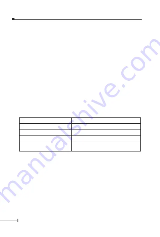
If attached device is:

100Base-TX port will set to:

•10Mbps, no auto-negotiation

10Mbps

•10Mbps, with auto-negotiation 

10/20Mbps (10Base-T/Full-Duplex)

•100Mbps, no auto-negotiation 

100Mbps

•100Mbps, with auto-negotiation  100/200Mbps 

(100Base-TX/Full-Duplex)

5. TROUBLESHOOTING

This chapter contains information to help you solve problems. If the Ethernet Switch is not 
functioning properly, make sure the Ethernet Switch was set up according to instructions 
in this manual.

The Link LED is not lit

Solution:

Check the cable connection and remove duplex mode of the Ethernet Switch

Содержание FGSW-1820RS

Страница 1: ...tion in this manual that is incorrect misleading or incom plete we would appreciate your comments and suggestions FCC Warning This equipment has been tested and found to comply with the limits for a C...

Страница 2: ...Revision PLANET 16 24 Port 10 100Mbps 2 Gigabit TP SFP combo Ethernet Smart Switch User s Manual FOR MODEL FGSW 1820RS FGSW 2620RS Rev 1 0 July 2006 Part No 2010 A81120 000...

Страница 3: ...STALLING A FGSW 1820RS FGSW 2620RS 7 3 CONSOLE CONFIGURATION 10 3 1 PREPARING FOR CONFIGURATION 10 3 2 GETTING STARTED 12 4 SWITCH OPERATION 29 4 1 ADDRESS TABLE 29 4 2 LEARNING 29 4 3 FORWARDING FILT...

Страница 4: ...This page is intentionally left blank...

Страница 5: ...10 100Mbps 2 Gigabit TP SFP combo Ethernet Smart Switch Users Manual is structured as follows Section 2 Installation It explains the functions of FGSW 1820RS FGSW 2620RS and how to physi cally install...

Страница 6: ...E frame flow control full duplex High performance Store and Forward architecture broadcast storm control runt CRC filtering eliminates erroneous packets to optimize the network band width 8K MAC addre...

Страница 7: ...802 3x Pause Frame for full duplex Dimensions 440 x 120 x 44 mm 1U height Weight FGSW 1820RS 1 46 kg FGSW 2620RS 1 57 kg Power Requirement 100 240 VAC 50 60 Hz Power Consumption Dissipation FGSW 1820R...

Страница 8: ...support QoS Allow to assign high priority on each port IGMP Snooping Allow to disable or enable Standards Conformance Regulation Compliance FCC Part 15 Class A CE Standards Compliance IEEE 802 3 Ether...

Страница 9: ...GSW 2620RS the Switch is Ethernet Smart Switch with 16 24 RJ 45 10 100Mbps ports The Switch also provides up to two 10 100 1000Mbps ports and 2 SFP interfaces for cost effective high performance netwo...

Страница 10: ...ort is operating at 10Mbps Per 10 100 1000Base T port SFP interfaces LED Color Function LNK ACT 1000 Green Lit indicate that the port is operating at 1000Mbps Off indicate that the port is operating a...

Страница 11: ...vice may also help to protect your Switch from being damaged by unregulated surge or current to the Switch or the power adapter 2 2 Installing the Switch This part describes how to install your Ethern...

Страница 12: ...a 19 inch standard rack follow the instructions described below Step1 Place your Switch on a hard at surface with the front panel positioned towards your front side Step2 Attach a rack mount bracket t...

Страница 13: ...9 Figure 2 5 Mounting the Switch in a Rack Step6 Proceed with the steps 4 and steps 5 of section 2 2 1 Desktop Installation to connect the network cabling and supply power to your Switch...

Страница 14: ...0RS 3 1 Preparing for con guration 3 1 1 Connecting a PC or Terminal to the RS 232 Port When you are ready to con gure the smart functions of the Switch make sure you had connected the supplied RS 232...

Страница 15: ...re The messages will be displayed to show the test progress When the test completes successfully the system will display a login screen If any of the components fails during the test you may need to c...

Страница 16: ...escription Value 1 7 Choose one item from the console main screen I M J L KEY Means up down left right 1 2 KEY Page up Page down S KEY Save the current configuration F KEY Refresh screen SPACE KEY Whe...

Страница 17: ...anagement purpose Explained in section 3 2 5 4 Diagnostics Allow user to view the information about the Trunk link warning and Network loop fault port detected Explained in section 3 2 6 5 Password Al...

Страница 18: ...ained in sec tion 3 2 3 3 Table 3 2 Descriptions of the Status screen Objects 3 2 3 1 Overview This function display the Switch information the available items are Switch name Switch MAC ID Chip Model...

Страница 19: ...ffic on each port P X KEY Start Stop polling T KEY Toggle Drop CRC Collision B KEY Toggle Byte Packet unit Table 3 3 Guideline within the MIB Counter screen 3 2 3 3 Port Status This function displays...

Страница 20: ...ion allow user to setting each port of Switch Explained in section 3 2 4 1 Trunking Allow user to disable or enable the trunk function Explained in section 3 2 4 2 Global Allow user to disable or enab...

Страница 21: ...ess S key to saving the current con guration Then press R to restart the Auto negotiation to ensure the setting activated immediately Table 3 6 describes the Port objects Item Description Enabled Allo...

Страница 22: ...Full 10M Full 10M Full 10M Half 10M Half 10M Half 10M Half 10M Half 10M Half 10M Half Link status of the device using Auto negotiation to the Switch Switch s Speed Advertise setting Device mode setti...

Страница 23: ...S key to saving the current con guration Figure 3 11 Trunking Screen Object Description Trunking Provide 6 8 trunk groups in FGSW 1820RS FGSW 2620RS maximum up to 4 ports per trunk Enable Allow disab...

Страница 24: ...or diagnose purpose Default Disable Table 3 8 Descriptions of the Global Screen Objects 3 2 4 4 QoS Press 4 on your keyboard to access the screen of QoS from the Con guration screen please see the gur...

Страница 25: ...ve in gure 3 14 appears Table 3 10 shows the descriptions of the Priority Tag Insert Remove screen Objects Figure 3 14 Priority Tag Insert Remove Screen Object Description Insert Tag high priority onl...

Страница 26: ...entire multicast group member Default disable 802 1Q VLAN tag aware Allow to disable or enable IEEE 802 1Q VLAN Tag aware Default disable Ingress Rule for Acceptable frame types To permit all frames o...

Страница 27: ...ed VLAN group 3 Please use L key move to specific port then press space key to add this port into current VLAN group 4 After setup completed please press Enter key to update the VLAN table 5 Please pr...

Страница 28: ...2 5 Security Press 3 on your keyboard to access the screen of Security from the Main Menu screen please see the gure 3 4 The screen of Con guration in gure 3 18 appears This function reserved for fur...

Страница 29: ...port Table 3 13 Diagnostics Screen Objects 3 2 7 Password Press 5 on your keyboard to access the screen of Password from the Main Menu screen please see the gure 3 4 The screen of Password in gure 3...

Страница 30: ...ress 2 key to change the password the screen in figure 3 23 3 24 appears Figure 3 23 Change password Screen 5 Please press Enter to execute current configuration Figure 3 24 Change password successful...

Страница 31: ...Reboot Switch Screen Reboot and reset switch to default mode procedure 1 Please press D key to reset switch to default mode the screen in figure 3 26 3 27 appears Figure 3 26 Reset Switch to default m...

Страница 32: ...default mode Not include the modi ed username and password Please memorize the new username and password after change it 3 2 9 Logout Press 7 on your keyboard to access the screen of Logout from the...

Страница 33: ...address learning The Ethernet Switching will lookup the address table for the destination address If not found this packet will be forwarded to all the other ports except the port which this packet c...

Страница 34: ...ad on the network The Switch performs Store and forward therefore no error packets occur More reliably it reduces the re transmission rate No packet loss will occur 4 5 Auto Negotiation The STP ports...

Страница 35: ...mance will be poor Please also check the in out rate of the port Why the Switch doesn t connect to the network Solution Check the LNK ACT LED on the switch Try another port on the Switch Make sure the...

Страница 36: ...7 8 Not used A 2 RJ 45 cable Pin Assignments The standard RJ 45 receptacle connector There are 8 wires on a standard UTP STP cable and each wire is color coded The following shows the pin allocation...

Страница 37: ......

Страница 38: ...Part No 2010 A81120 000...

Отзывы: