Planet FGSW-1820CS Скачать руководство пользователя страница 4


- 4 - 


1.  INTRODUCTION 

1.1 Checklist 

Check the contents of your package for following parts: 

z


FGSW-1820CS or FGSW-2620CS x1 

z


Quick Installation Guide x1 

z


User's manual CD x1 

z


Power cord x 1 

z


Rubber feet x 4 

z


Two rack-mounting brackets with attachment screws x1 

 
If any of these pieces are missing or damaged, please contact your dealer immediately, if possible, retain the carton 
including the original packing material, and use them against to repack the product in case there is a need to return it to 
us for repair. 

In the following section, the term 

“Web Smart Switch”

 means the two Switch devices, ie. FGSW-1820CS and 

FGSW-2620CS; term of 

“switch”

 can be any third switches. 

1.2 About the Switch 

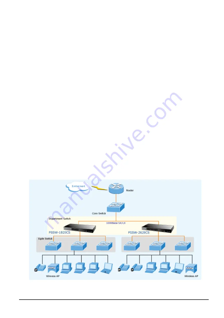
The FGSW-1820CS / FGSW-2620CS provide 16/24 10/100Mbps Fast Ethernet ports and two Gigabit Ethernet ports, 

either TP or SFP per port. The two Gigabit ports either can be 1000Base-T for 10/100/1000Mbps or 1000Base-SX/LX 

through SFP (Small Factor Pluggable) interfaces. The distance can be extended from 100 meters (TP), 550 meters 

(Multi-mode fiber), up to above 10/20/30/40/50/70/120 kilometers (Single-mode fiber).  

The FGSW-1820CS / FGSW-2620CS, equipped with non-blocking 7.2 / 8.8Gbps backplane, greatly simplifies the tasks of 

upgrading your LAN for catering to increase bandwidth demands. 


For efficient management, the FGSW-1820CS / FGSW-2620CS 16/24-Port 10/1 2 Gigabit TP / SFP Combo 

Web Smart Switch is equipped with remote Web interface. The FGSW-1820CS / FGSW-2620CS can be programmed for 

Содержание FGSW-1820CS

Страница 1: ...User s Manual FGSW 1820CS FGSW 2620CS 16 24 Port 10 100Mbps with 2 Gigabit TP SFP Combo Web Smart Switch 1 ...

Страница 2: ... comments and suggestions FCC Warning This equipment has been tested and found to comply with the limits for a Class A digital device pursuant to Part 15 of the FCC Rules These limits are designed to provide reasonable protection against harmful interference when the equipment is operated in a commercial environment This equipment generates uses and can radiate radio frequency energy and if not in...

Страница 3: ...T 27 4 3 1 Port Configuration 28 4 3 2 Port Mirroring 30 4 3 3 Bandwidth Control 31 4 3 4 Broadcast Storm Control 32 4 3 5 Port Statistics 33 4 4 VLAN SETTING 34 4 4 1 Port Based VLAN 37 4 4 2 Port Based VLAN Setting example 38 4 4 3 802 1Q VLAN 39 4 4 4 802 1Q VLAN Setting example 42 4 4 5 MTU VLAN 48 4 5 TRUNK 49 4 6 QOS SETTING 51 4 6 1 Priority Mode 52 4 6 2 Class of Service Configuration 53 4...

Страница 4: ...of switch can be any third switches 1 2 About the Switch The FGSW 1820CS FGSW 2620CS provide 16 24 10 100Mbps Fast Ethernet ports and two Gigabit Ethernet ports either TP or SFP per port The two Gigabit ports either can be 1000Base T for 10 100 1000Mbps or 1000Base SX LX through SFP Small Factor Pluggable interfaces The distance can be extended from 100 meters TP 550 meters Multi mode fiber up to ...

Страница 5: ...ugh or crossover 1 3 Features Complies with the IEEE 802 3 IEEE 802 3u IEEE 802 3ab IEEE 802 3z Gigabit Ethernet standard 16 24 Port 10 100Mbps Fast Ethernet Switch 2 10 100 1000Mbps ports share with 2 SFP interfaces Each Switching ports support auto negotiation 10 20 100 200Mbps Fast Ethernet 1000 2000Mbps Gigabit Ethernet supported Auto MDI MDI X detection on each RJ 45 port Prevents packet loss...

Страница 6: ...watts 64BTU Temperature Operating 0 50 degree C Storage 40 70 degree Humidity Operating 5 to 90 Storage 5 to 90 Non condensing Smart function System Configuration Web interface Port configuration Port speed duplex mode selection Flow control disable enable Port dis able enable Port description on each port Bandwidth Control Yes 1 2 4 8 16 32 64Mbps Broadcast Storm Control Yes 5 10 25 50 Disable Po...

Страница 7: ...ards Conformance Regulation Compliance FCC Part 15 Class A CE Standards Compliance IEEE 802 3 Ethernet IEEE 802 3u Fast Ethernet IEEE 802 3ab Gigabit Ethernet IEEE 802 3z Gigabit Ethernet IEEE 802 3x Full duplex flow control IEEE 802 1Q VLAN IEEE 802 1p QoS ...

Страница 8: ...ont panel Figure 2 2 FGSW 2620CS Switch front panel 2 1 1 LED indicators System LED Color Function PWR Green Lights to indicate that the Switch has power Per 10 100Mbps port LED Color Function LNK ACT Green Lights to indicate the link through that port is established at 10 100Mbps full duplex mode Blink slowly to indicate the link through that port is established at 10 100Mbps half duplex mode Bli...

Страница 9: ...t Switch on a desktop or shelf simply completed the following steps 2 3 1 Desktop Installation To install Web Smart Switch on a desktop or shelf simply completed the following steps Step 1 Attached the rubber feet to the recessed areas on the bottom of the Web Smart Switch Step 2 Place the Web Smart Switch on a desktop or shelf near an AC power source Step 3 Keep enough ventilation space between t...

Страница 10: ...ews would invalidate your warranty Step 3 Secure the brackets tightly Step 4 Follow the same steps to attach the second bracket to the opposite side Step 5 After the brackets are attached to the Web Smart Switch use suitable screws to securely attach the brackets to the rack as shown in Figure 2 5 Figure 2 5 Mounting the Web Smart Switch in a Rack Step 6 Precede with the steps 4 and steps 5 of sec...

Страница 11: ...ith one side must be male duplex LC connector type To connect to 1000Base LX SFP transceiver use the single mode fiber cable with one side must be male duplex LC connector type Connect the fiber cable 1 Attach the duplex LC connector on the network cable into the SFP transceiver 2 Connect the other end of the cable to a device switches with SFP installed fiber NIC on a workstation or a Media Conve...

Страница 12: ... out the SFP transceiver Notice Never pull out the module without pull the handle or the push bolts on the module Direct pull out the module with violent could damage the module and SFP module slot of the Web Smart Switch ...

Страница 13: ...agement of the Switch please note the Switch is configured through an Ethernet connection make sure the manager PC must be set on the same IP subnet address for example the default IP address of the Switch is 192 168 0 100 the factory default IP address then the manager PC should be set at 192 168 0 x where x is a number between 1 and 254 except 100 and the default subnet mask is 255 255 255 0 Use...

Страница 14: ... information from the devices such as MAC Address Device Name firmware version Device IP Subnet address also can assign new password IP Subnet address and description for the devices 4 After setup completed press Update Device Update Multi or Update All button to take affect The meaning of the 3 buttons above are shown as below Update Device use current setting on one single device Update Multi us...

Страница 15: ...rt Discovery Utility 3 3 Logging on to the FGSW 1820CS FGSW 2620CS When you log on to the Web Smart Switch Web interface for the first time a sign on string appears and you are prompted for a Web login username and password Figure 3 3 Web Smart Switch Web Login Screen The factory default login username and password is admin Notice 1 For FGSW 1820CS the display will be the same to FGSW 2620CS 2 For...

Страница 16: ... on the console screens of FGSW 2620CS for FGSW 1820CS the display will be the same to FGSW 2620CS 4 1 Login in to the Switch To access the Web browser interface you must first enter the user name and password the default user name and password is admin You will see the following screen comes out on the Web browser program Figure 4 1 Web Login Screen After the User name and Password is entered you...

Страница 17: ...ection 4 3 VLAN Setting Provide VLAN Setting configuration of Web Smart Switch Explained in section 4 4 Trunk Setting Provide Trunk Setting configuration of Web Smart Switch Explained in section 4 5 QoS Setting Provide QoS Setting configuration of Web Smart Switch Explained in section 4 6 Security Provide Security configuration of Web Smart Switch Explained in section 4 7 Misc Operation Provide Mi...

Страница 18: ...on Display the MAC address Hardware Version and Software Version Device Description Ex plained in section 4 2 1 IP Configuration Allow to change the IP subnet address of Web Smart Switch Explained in section 4 2 2 Password Setting Allow to change the username and password of Web Smart Switch Explained in section 4 2 3 Factory Default Allow reset the Web Smart Switch to factory default mode Explain...

Страница 19: ...ess Hardware Version and Software Version also allow define the device description and press Apply button to take affect The screen in Figure 4 4 appears Figure 4 4 System Information Web Page Screen Notice Up to 16 characters is allowed for the Device Description ...

Страница 20: ...P Configuration Web Page Screen After setup complete and press Apply button to take affect The following screen in Figure 4 6 appears and then another Web page login screen with new IP address will show up After input correct username and password then can continue the Web Smart Switch management Figure 4 6 IP Configuration Web Page Screen ...

Страница 21: ...ord Setting This section provides change the Username and Password the screen in Figure 4 7 appears Figure 4 7 Password Setting Web Page Screen Notice Up to 8 characters is allowed for the username and password assign ...

Страница 22: ...gure 4 8 Factory Default Web Page Screen Press Factory Default button to take affect The following screen in Figure 4 9 appears and then another Web page login screen with default setting will show up After input default username and password then can continue the Web Smart Switch management Figure 4 9 Factory Default Web Page Screen ...

Страница 23: ...are upgrade of the Web Smart Switch the screen in Figure 4 10 appears Figure 4 10 Firmware Update Web Page Screen Press Update button for start the firmware upgrade process the screen in Figure 4 11 4 12 appears Figure 4 11 Firmware Update Web Page Screen ...

Страница 24: ...12 Firmware Update Web page Screen Then the following screen appears press Browser button to find the firmware location administrator PC the screen in Figure 4 13 appears Figure 4 13 Firmware Update Web Page Screen ...

Страница 25: ... 14 Firmware Update Web Page Screen When firmware upgrade process is completed then the following screen appears please wait for a while for system reboot After device reboot then can use the latest firmware of the Web Smart Switch Figure 4 15 Firmware Update Web Page Screen Notice Recommend to use IE 6 0 or FireFox browser tools for firmware upgrade process ...

Страница 26: ...een in Figure 4 16 appears Figure 4 16 Reboot Web Page Screen Press Reboot button to reboot the Web Smart Switch the screen in Figure 4 17 appears After device reboot completed the Web login screen appears and login for further management Figure 4 17 Reboot Web Page Screen ...

Страница 27: ...reen Objects Object Description Port Configuration Allow to configure each port of Web Smart Switch Explained in section 4 3 1 Port Mirroring Allow to use port mirroring function of Web Smart Switch Explained in section 4 3 2 Bandwidth Control Allow to configure bandwidth control of each port from Web Smart Switch Explained in section 4 3 3 Broadcast Storm Control Allow to configure broadcast stor...

Страница 28: ...il settings of per port on Web Smart Switch the screen in Figure 4 19 4 20 appears and Table 4 3 4 4 descriptions the Port Configuration objects of Web Smart Switch Figure 4 19 Port Configuration Web Page Screen Figure 4 20 Port Configuration Web Page Screen ...

Страница 29: ...le and Disable Default mode is Enable Port Description Allow input per Port Description of Web Smart Switch up to maximum 8 characters allow Apply button Press Apply button for save current configuration of each port on Web Smart Switch Object Description Port Indicate port 1 to port 26 FGSW 2620CS port 1 to port 18 FGSW 1820CS Current Status Display per port Current Status such as Link Speed Mode...

Страница 30: ... Screen Objects Object Description Monitored Packets Provide disable and enable the Port Mirroring function the available options are Disable RX TX TX RX Default mode is Disable Destination Port The destination port can be used to see all monitor port traffic It can connect destination port to LAN analyzer or Netxray Source Port The source port that want to monitor All monitor port traffic will be...

Страница 31: ...jects Object Description Port Indicate port 1 to port 24 FGSW 2620CS port 1 to port 16 FGSW 1820CS Tx Rate Provide No Limit 1Mbps 2Mbps 4Mbps 8Mbps 16Mbps 32Mbps 64Mbps different transmit rate for bandwidth control function of Web Smart Switch Default mode is No Limit Rx Rate Provide No Limit 1Mbps 2Mbps 4Mbps 8Mbps 16Mbps 32Mbps 64Mbps different re ceive rate for bandwidth control function of Web...

Страница 32: ...7 descriptions the Broadcast Storm Control objects of Web Smart Switch Figure 4 23 Broadcast Storm Control Web Page Screen Table 4 7 Descriptions of the Broadcast Storm Control Screen Objects Object Description Filter Mode Provide 5 10 25 50 Disable different filter mode Default mode is Disable Apply button Press this button for save current configuration of Web Smart Switch ...

Страница 33: ...of Ethernet traffic counter mode the available options are shown as below Receive Packet Transmit Packet collision Count Transmit Packet Drop Packet Receive Packet CRC error Packet Receive Packet Default mode is Receive Packet Transmit Packet Port Indicate port 1 to port 26 FGSW 2620CS port 1 to port 18 FGSW 1820CS Transmit Display Transmit count value from each port Receive Display Receive count ...

Страница 34: ...unknown sources VLAN can also provide a level of security to your network IEEE 802 1Q VLAN will only deliver packets between stations that are members of the VLAN Any port can be configured as either tagging or untagging The untagging feature of IEEE 802 1Q VLAN allows VLAN to work with legacy switches that don t recognize VLAN tags in packet headers The tagging feature allows VLAN to span multipl...

Страница 35: ...kets are forwarded according to the VID contained within the tag Tagged packets are also assigned a PVID but the PVID is not used to make packet forwarding decisions the VID is Tag aware switches must keep a table to relate PVID within the switch to VID on the network The switch will compare the VID of a packet to be transmitted to the VID of the port that is to transmit the packet If the two VID ...

Страница 36: ...ing Web Page Screen Table 4 9 Descriptions of the VLAN Setting Screen Objects Object Description VLAN Mode Provide different VLAN operation mode the available options are shown as below No VLAN Port Based VLAN Explained in section 4 4 1 802 1Q VLAN Explained in section 4 4 3 MTU Explained in section 4 4 5 Default mode is No VLAN Apply button Press this button for save current configuration of Web ...

Страница 37: ...ed VLAN from VLAN from the VLAN Mode and press Apply button to enable the port based VLAN function The screen in Figure 4 26 4 27 4 28 appears and Table 4 10 description the Port Based VLAN objects of Web Smart Switch Figure 4 26 Port Based VLAN Configuration Web Page Screen Figure 4 27 Port Based VLAN Configuration Web Page Screen ...

Страница 38: ...t 25 i e 3 26 4 26 25 26 Object Description VID Display different VLAN ID from multi port based VLAN groups VLAN Name Assign and display different VLAN name from multi port based VLAN groups Up to maximum 8 characters allow Port Indicate port 1 to port 26 FGSW 2620CS port 1 to port 18 FGSW 1820CS Member Allow to click specific port as member port from different port based VLAN groups Apply button ...

Страница 39: ...ort 25 4 4 3 802 1Q VLAN This section introduces detail information of IEEE 802 1Q VLAN function of Web Smart Switch Choose 802 1Q VLAN from VLAN from the VLAN Mode and press Apply button to enable the 802 1Q VLAN function The screen in Figure 4 29 4 30 4 31 appears and Table 4 11 description the 802 1Q VLAN objects of Web Smart Switch Figure 4 29 802 1Q VLAN Configuration Web Page Screen Figure 4...

Страница 40: ...ers allow Port Indicate port 1 to port 26 FGSW 2620CS port 1 to port 18 FGSW 1820CS Member Allow to click specific port as member port from different 802 1Q VLAN groups Apply button Press this button for save current configuration of Web Smart Switch Per Port Setting Allow to define per port UnTag Tag Uplink and PVID The screen in Figure 4 32 appears Delete Group Press this button for delete exist...

Страница 41: ...etting Screen Objects Object Description Port Indicate port 1 to port 26 FGSW 2620CS port 1 to port 18 FGSW 1820CS Link Type Define UnTag or Tag on each port of Web Smart Switch Default mode is UnTag Uplink Define No Uplink or Uplink on each port of Web Smart Switch Default mode is No Uplink PVID Assign PVID on each port of Web Smart Switch Default PVID is 1 Apply button Press this button for save...

Страница 42: ...C 4 PC 5 and PC 6 received no packet 3 While the packet leaves Port 2 it will be stripped away it tag becoming an untagged packet 4 While the packet leaves Port 3 it will keep as a tagged packet with VLAN Tag 2 Tagged packet entering VLAN 2 5 While PC 3 transmit a tagged packet with VLAN Tag 2 enters Port 3 PC 1 and PC 2 will received the packet through Port 1 and Port 2 6 While the packet leaves ...

Страница 43: ...two VLANs VLAN 2 and VLAN 3 VLAN Group 2 with VID 2 VLAN Group 3 with VID 3 Figure 4 34 Add new VLAN Group Screen 2 Assign VLAN Member VLAN 2 Port 1 Port 2 and Port 3 VLAN 3 Port 4 Port 5 and Port 6 VLAN 1 All other ports Port 7 Port 24 Figure 4 35 Assign VLAN members for VLAN 2 and VLAN 3 ...

Страница 44: ...from VLAN 1 membership since the Port 1 Port 6 had been assigned to VLAN 2 and VLAN 3 Figure 4 36 Remove specify ports from VLAN 1 member Notice Its import to remove the VLAN member port from VLAN 1 group Or the ports would become overlapping setting ...

Страница 45: ...igure 4 37 appears Figure 4 37 Port 1 Port 6 802 1Q VLAN Configuration Two separate 802 1Q VLAN with overlapping area scenario 1 Based on the two separate VLAN group examples above VLAN 2 and VLAN 3 member port cannot see each other 2 The member ports from VLAN 2 and VLAN 3 need to access one public server Figure 4 38 A Server connect to the VLAN overlapping area 1 Specify Port 7 on the Web Smart ...

Страница 46: ...the VLAN Member configuration page The screen in Figure 4 39 appears Figure 4 39 VLAN overlap port setting 3 Define a VLAN 1 as a Public Area that overlapping with both VLAN 2 members and VLAN 3 members Figure 4 40 VLAN 1 The public area member assign ...

Страница 47: ...screen in Figure 4 41 appears Figure 4 41 Setup Port 7 with PVID 1 Although the VLAN 2 members Port 1 to Port 3 and VLAN 3 members Port 4 to Port 6 also belongs to VLAN 1 But with different PVID settings packets form VLAN 2 or VLAN 3 is not able to access to the other VLAN ...

Страница 48: ...n Figure 4 42 appears and Table 4 14 description the MTU VLAN objects of Web Smart Switch Figure 4 42 MTU VLAN Configuration Web Page Screen Table 4 14 Descriptions of the MTU VLAN Setting Screen Objects Object Description MTU Port Indicate the MTU Port of Web Smart Switch Member Port Indicate the Member Port of Web Smart Switch Apply button Press this button for save current configuration of Web ...

Страница 49: ... assigned to the same link aggregation have certain other restrictions see below Ports can only be assigned to one link aggregation The ports at both ends of a connection must be configured as link aggregation ports None of the ports in a link aggregation can be configured as a mirror source port or a mirror target port Enable the link aggregation prior to connecting any cable between the switches...

Страница 50: ...eb Smart Switch Figure 4 43 Trunk Setting Web Page Screen Table 4 15 Descriptions of the Trunk Setting Screen Objects Object Description Trunk Hash Algorithm selection Provide four various Trunk Hash Algorithm polices the available options are shown as below SA DA Default Port ID SA DA Default mode is SA DA Trunk1 Indicate the Trunk Member Port 1 2 3 4 of Web Smart Switch Trunk2 Indicate the Trunk...

Страница 51: ...Screen Table 4 16 Descriptions of the QoS Setting Screen Objects Object Description Priority Mode Provide three different Priority polices on Web Smart Switch Explained in section 4 6 1 Class of Service Con figuration Provide three different polices on each port of Web Smart Switch Explained in section 4 6 2 TCP UDP Port Based QoS Allow to define various QoS mode on TCP UDP port Explained in secti...

Страница 52: ... Mode Web Page Screen Table 4 17 Descriptions of the Priority Mode Screen Objects Object Description Priority Mode Provide three different Priority polices on Web Smart Switch the available options are shown as below Fist In First Out All High Before Low Weight Round Robin Low weight 0 7 range High weight 0 7 range Default mode is First In First Out Apply Press this button for save current configu...

Страница 53: ...define IEEE 802 1p priority value from VLAN tag High Priority User priority values 4 7 Low Priority User priority values 0 3 Object Description Enable High Priority Allow to disable or enable the High Priority function Default mode is Enable Port Indicate port 1 to port 26 FGSW 2620CS port 1 to port 18 FGSW 1820CS Port Base Define per port Class of Service policy based on Port Base policy VLAN Tag...

Страница 54: ...OS DSCP Value High Priority EF DSCP 46 101110 AF11 DSCP 10 001010 AF21 DSCP 18 010010 AF31 DSCP 26 011010 AF41 DSCP 34 100010 Low Priority Other DSCP values DSCP Differentiated Services Code Point EF Expected Forwarding AF Assured Forwarding ...

Страница 55: ...d QoS Configuration of Web Smart Switch the screen in Figure 4 47 4 48 appears and Table 4 19 descriptions the TCP UDP Port Based QoS Configuration of Web Smart Switch Figure 4 47 TCP UDP Port Based QoS Configuration Web Page Screen Figure 4 48 TCP UDP Port Based QoS Configuration Web Page Screen ...

Страница 56: ...TTPS 443 Provide F I F O Discard Low High options MSN 1863 Provide F I F O Discard Low High options XRD_RDP 3389 Provide F I F O Discard Low High options QQ 4000 8000 Provide F I F O Discard Low High options ICQ 5190 Provide F I F O Discard Low High options Yahoo 5050 Provide F I F O Discard Low High options BOOTP_DHCP 67 68 Provide Low High options User_Define_a Provide F I F O Discard Low High o...

Страница 57: ... Web Smart Switch Figure 4 49 Security Filter Web Page Screen Table 4 20 Descriptions of the Security Filter Web Page Screen Objects Object Description MAC Address Filter Allow define three MAC Address on per port of Web Smart Switch Explained in section 4 7 1 TCP UDP Filter Allow define the filter policy of TCP UDP flow on Web Smart Switch Explained in section 4 7 2 ...

Страница 58: ...per port of Web Smart Switch Select Port Allow to select port 1 to port 26 FGSW 2620CS or port 1 to port 18 FGSW 1820CS Binding Allow to Disable or Enable the binding function on each port of Web Smart Switch Apply Press this button for save current configuration of Web Smart Switch Object Description Port Indicate port 1 to port 26 FGSW 2620CS port 1 to port 18 FGSW 1820CS Binding Status Display ...

Страница 59: ... information of TCP UDP Filter of Web Smart Switch the screen in Figure 4 51 4 52 appears and Table 4 23 descriptions the TCP UDP Filter Configuration of Web Smart Switch Figure 4 51 TCP UDP Filter Web Page Screen Figure 4 52 TCP UDP Filter Web Page Screen ...

Страница 60: ...he TCP UDP Filter policy FTP 20 21 SSH 22 TELNET 23 SMTP 25 DNS 53 TFTP 69 HTTP 80 8080 POP3 110 NEWS 119 SNTP 123 NetBIOS 137 139 IMAP 143 220 SNMP 161 162 HTTPS 443 MSN 1863 XRD_RDP 3389 QQ 4000 8000 ICQ 5190 Yahoo 5050 BOOTP_DHCP 67 68 User_Define_a User_Define_b User_Define_c User_Define_d Allow to choose list protocol for filtering Secure Egress Port Indicate port 1 to port 26 FGSW 2620CS por...

Страница 61: ...s Object Description Output Queue Aging Time Allow define the Output Queue Aging Time of Web Smart Switch the available options are Disable 200ms 400ms 600ms and 800ms Default mode is Disable VLAN Striding Allow Disable or Enable the VLAN Striding function of Web Smart Switch Default mode is Disable IGMP Snooping V1 V2 Allow Disable or Enable the IGMP Snooping V1 V2 function of Web Smart Switch De...

Страница 62: ...fter choose this function and the following screen appears in Figure 4 54 4 55 Please press Logout button to take effect and Login Web Screen appears Please re login the Web Smart Switch for further management Figure 4 54 Logout Web Page Screen Figure 4 55 Login Web Page Screen ...

Страница 63: ...r do the complete error checking before transmission Therefore no error packets occurrence it is the best choice when a network needs efficiency and stability The Ethernet Switch scans the destination address from the packet header searches the routing table provided for the incoming port and forwards the packet only if required The fast forwarding makes the switch attractive for con necting serve...

Страница 64: ...er is set to half duplex then the performance will be poor 100Base TX port link LED is lit but the traffic is irregular Solution Check that the attached device is not set to dedicate full duplex Some devices use a physical or software switch to change duplex modes Auto negotiation may not recognize this type of full duplex setting Why the Switch doesn t connect to the network Solution Check the LN...

Страница 65: ..._DC BI_DD 6 BI_DB BI_DA 7 BI_DD BI_DC 8 BI_DD BI_DC 10 100Mbps 10 100Base TX RJ 45 Connector pin assignment Contact MDI Media Dependant In terface MDI X Media Dependant Interface Cross 1 Tx transmit Rx receive 2 Tx transmit Rx receive 3 Rx receive Tx transmit 4 5 Not used 6 Rx receive Tx transmit 7 8 Not used A 2 RJ 45 cable pin assignment 21 3 6 1 2 3 6 21 3 6 The standard RJ 45 receptacle connec...

Страница 66: ...ng shows the pin allocation and color of straight cable and crossover cable connection Figure A 1 Straight Through and Crossover Cable Please make sure your connected cables are with same pin assignment and color as above picture before deploying the cables into your network 2080 A81150 000 ...

Страница 67: ...C 92 31 EEC 93 68 EEC For the evaluation regarding the EMC the following standards were applied Emission EN 50081 1 1992 Conducted Radiated EN 55022 1998 Harmonic EN 61000 3 2 1995 Flicker EN 61000 3 3 1995 Immunity EN 55024 1998 ESD EN 61000 4 2 1995 RS EN 61000 4 3 1996 EFT Burst EN 61000 4 4 1995 Surge EN 61000 4 5 1995 CS EN 61000 4 6 1996 Voltage Disp EN 61000 4 11 1994 Responsible for markin...

Страница 68: ...5024 1998 A1 2001 A2 2003 ESD IEC 61000 4 2 1995 A1 1998 A2 2001 RS IEC 61000 4 3 1995 A1 1998 A2 2001 EFT Burst IEC 61000 4 4 1995 A1 2001 A2 2001 Surge IEC 61000 4 5 1995 A1 2001 CS IEC 61000 4 6 1996 A1 2001 Magnetic Field IEC 61000 4 8 1993 A1 2001 Voltage Disp IEC 61000 4 11 1994 A1 2001 Responsible for marking this declaration if the Manufacturer Authorized representative established within ...

Отзывы: