


7
Chapter 2 Display Controls
User Controls
A brief description and the location of all LCD Monitor function controls and indicators:
8
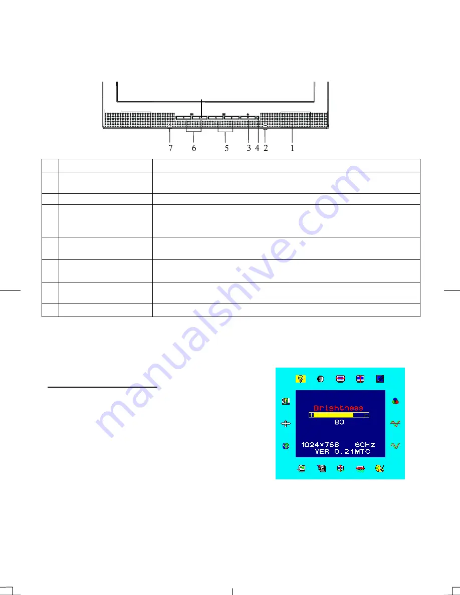
Figure 2-1
1 Stereo
Speakers
PC Audio Stereo output.
2
Speaker Volume
Control
Increase Volume - Turn knob clockwise.
Decrease Volume - Turn knob counter clockwise
3 DC Power Switch
Press the power switch to switch the monitor ON/OFF.
4
DC Power-On
Indicator
LED lights Green color --- Power is ON.
LED lights Yellow --- Monitor is in "Power Saving Mode".
LED is off --- Power is OFF.
5
Function Select
Buttons
Press either left or right control button for OSD (On Screen Display)
menu selection.
6
Adjustment Control
Buttons
Press the left button to decrease the OSD setting and press the right
button to increase the OSD setting.
7
External Headphone
Jack
The monitor speakers will be disabled when using an external
headphone or external speakers.
8 Input
Select
Press this button to switch between Analog or Digital input.
Adjusting the Monitor's Display
The monitor has four function control buttons to select among functions shown on OSD menu,
designed for easy user-viewing environments.
OSD Function Menu
To access OSD Main menu, simply press one of the Function
Select control buttons, and the menu diagram will pop up on the
screen as shown on Fig. 2-2:
Continue pressing the Function Select buttons to scroll through
the entire menu items ,then press Adjustment Control buttons to
adjust content of selected item.
Figure 2-2
Attention
Firmware revision may have been updated into a latest version while the version number
shown on all OSD menus in this manual will stay as Ver. 1.00.
Содержание PL1711M
Страница 1: ...PL1711M ...


