background image

LC640.480.33-AC Operations Manual (OM600-01)

23

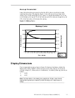
Warm-up Characteristic

Some time after startup is required to allow the CCFL tubes to reach their normal
operating temperature. The graph in Figure 14 shows the typical room temperature
warmup curve for the LC640.480.33-AC when set to maximum luminance. As can be
seen, luminance is at nearly 95% of the final value after five minutes of operation, and
99% of the final value at 10 minutes after startup.

Figure 14. Warmup Curve.

Display Dimensions

The recommended clearance shown in Figure 15 illustrates the distance behind the
display ECA which should be left for free low of air for the purposes of convection
cooling. In Figure 15, dimensions are in millimeters. Tolerances unless specified are as
follows:
.x

±

0.50

.xx

±

0.25

Note:

 The dimensions in this drawing are approximate. Please contact Planar

Applications Engineering to request the actual drawing prior to beginning your
design.

Warmup Curve

0

20

40

60

80

100

0

2

4

6

8 10 12 14 16 18 20 22 24 26 28 30 32 34

Time, minutes

Center Lu

m

inance, 

%

20.0

20.5

21.0

21.5

22.0

22.5

23.0

Backlight P

wr, W

Lum, %

PH

Содержание LC640.480.33-AC

Страница 1: ...Operations Manual LC640 480 33 AC HIGH BRIGHTNESS 10 4 COLOR TFT AMLCD The Definition of Quality ...

Страница 2: ...ks ColorBrite is a trademark of Planar Systems Inc This document is subject to change without notice Planar provides this information as reference only and does not imply any recommendation or endorsement of other vendor s products Revision Control Date Description May 1999 Document number OM600 01 ...

Страница 3: ... and Operation 8 Control Basics 8 Power Requirements 8 Undervoltage Lockout Backlight only 8 Power Sequencing LCD only 8 Backlight Signals 9 Video Signals 10 Video Signal Characteristics 10 Video Modes 10 Signal Timing 11 Video Characteristics 15 Pixel Position 16 Connectors 16 Video Connector J3 17 Dimming Connector J2 18 Backlight Power Connector J1 18 Optical Features 19 Viewing Angle 19 Respon...

Страница 4: ...emperature 22 Figure 14 Warmup Curve 23 Figure 15 Display Dimensions 24 Tables Table 1 Mounting Hardware 4 Table 2 Environmental Characteristics 6 Table 3 Mechanical Characteristics 6 Table 4 Optical Characteristics 7 Table 5 Backlight Life 7 Table 6 Input Power 8 Table 7 Backlight Signal DC Characteristics 9 Table 8 Video Signal DC Characteristics 10 Table 9 Video Modes 10 Table 10 Video signal t...

Страница 5: ...wo subassemblies The LCD subassembly includes a sealed optical cavity and the backlight inverter subassembly includes a cold cathode fluorescent CCFL backlight and inverter Due to the sealed optical cavity the backlight subassembly may be replaced without exposing the back of the LCD cell and optical films to airborne contaminants Features and Benefits 1000 nit typical luminance for sunlight reada...

Страница 6: ...rdware Screw 6 SS hex head or hex washer head or M3 SS hex head or hex washer head Washer Bearing washer for display face down bearing application only Lockwasher external type Tightening torque 4 oz in 2 8x10⁵ dyne cm Mounting Display Face Down Standoff spacers with a minimum height of 0 102 2 59 mm must be used at all four mounting locations to prevent binding and deflection of the display Threa...

Страница 7: ...ht Sensor Clearance Two backlight dimming modes utilize automatic brightness control ABC If the display is to be operated in either of these modes the ambient light sensor located on the front bezel must be unobstructed If the sensor is placed behind the same protective window as the display active viewing area the sensor operation may be affected due to light scattering and reflections from displ...

Страница 8: ...Operating 95 RH 40 ºC Non condensing per IEC 68 2 3 Altitude Operating 10K ft per IEC 68 2 13 Non operating 40K ft per IEC 68 2 13 Vibration random Operating 0 02 g 2 Hz 5 500 Hz 30 min ea axis per IEC 68 2 34 Shock Operating 100 g 6 ms half sine wave 3 shocks per surface per IEC 68 2 27 Mechanical Characteristics Refer to mechanical outline drawing in Figure 15 on page 24 Table 3 Mechanical Chara...

Страница 9: ...ield of view Dynamic range Visible light filtered 420 to 675nm 50 pts 50 degrees typical to half sensitivity 0 to 3000 Lux typ assumes 18 scene reflectance Viewing Angle Horizontal Vertical 70 degrees typ White black CR 5 40 60 degrees typ White black CR 5 See Figure 10 Safety and EMI The display will not inhibit the end product from compliance with UL1950 CSA22 2 and IEC950 The display will not i...

Страница 10: ... Absolute max voltage VLMAX 0 6 0 Vdc VL permissible ripple VL 5V VL 100 mVpp Current VL 5V IL 280 450 mAdc Power VL 5V PL 1 4 2 3 W CAUTION Absolute maximum ratings are those values beyond which damage to the device may occur Undervoltage Lockout Backlight only An undervoltage lockout UVLO function is included which disables the backlight under excessively low VH conditions The UVLO circuit will ...

Страница 11: ...equencing procedure should be followed Figure 3 VL Supply Dropouts td Vcc 4 5V 2 7V where td 10ms Backlight Signals The dimming control and DISABL inputs are analog though the latter is intended to be driven from either an open collector device or CMOS logic The ABCOFF input is a CMOS compatible digital input Table 7 Backlight Signal DC Characteristics Description Min Max Units Symbol Absolute max...

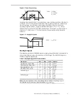
Страница 12: ...signals R L and U D 2 IIH1 applies to all signals except ENAB U D and R L IIH2 applies to signals ENAB U D and R L Video Modes The video interface automatically recognizes 480 400 and 350 line formats Mode recognition depends on the polarity of the sync signals as shown in Table 9 Table 9 Video Modes Mode 480 line 400 line 350 line Hsync J3 3 negative negative positive Vsync J3 4 negative positive...

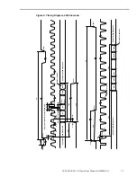
Страница 13: ...lock Hsync to Enable THe 44 TH 664 clock Table 11 below summarizes timing for the different vertical modes given typical vertical sync cycle TV values In this table data for line TVn is displayed as the first top row on the screen Table 11 Vertical mode video signal timing Mode Symbol 480 line 400 line 350 line V data start TVs 34 34 61 V data period TVd 480 400 350 V display start TVn 34 443 TV 4...

Страница 14: ...TV TVd 0 3Vcc Number of line 0 7Vcc 34 Tcp TVs TVp Tcs TVh 0 3Vcc 0 7Vcc Vertical invalid data period THc THd Horizontal invalid data period 0 7Vcc Horizontal invalid data period 0 3Vcc Number of H data 0 3Vcc 0 3Vcc TH D640 D639 D3 D2 D1 C1 1 2 0 3Vcc 0 3Vcc 0 7Vcc THc 0 3Vcc 0 3Vcc 0 3Vcc 0 3Vcc C2 C104 Number of clock 0 7Vcc Tc Tch THp Only when enable terminal is fixed low ...

Страница 15: ...TV TVd 0 3Vcc Number of line 0 3Vcc 34 Tcp TVs TVp Tcs TVh 0 7Vcc 0 7Vcc Vertical invalid data period THc THd Horizontal invalid data period 0 7Vcc Horizontal invalid data period 0 3Vcc Number of H data 0 3Vcc 0 3Vcc TH D640 D639 D3 D2 D1 C1 1 2 0 3Vcc 0 3Vcc 0 7Vcc THc 0 3Vcc 0 3Vcc 0 3Vcc 0 3Vcc C2 C104 Number of clock 0 7Vcc Tc Tch THp Only when enable terminal is fixed low ...

Страница 16: ...TV TVd 0 3Vcc Number of line 0 7Vcc 61 Tcp TVs TVp Tcs TVh 0 3Vcc 0 7Vcc Vertical invalid data period THc THd Horizontal invalid data period 0 7Vcc Horizontal invalid data period 0 7Vcc Number of H data 0 3Vcc 0 3Vcc TH D640 D639 D3 D2 D1 C1 1 2 0 7Vcc 0 7Vcc 0 3Vcc THc 0 3Vcc 0 3Vcc 0 3Vcc 0 3Vcc C2 C104 Number of clock 0 7Vcc Tc Tch THp Only when enable terminal is fixed low ...

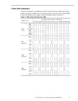
Страница 17: ...1 1 1 1 1 1 1 1 1 1 1 1 1 0 0 0 0 0 0 1 1 1 1 1 1 0 0 0 0 0 0 1 1 1 1 1 1 0 0 0 0 0 0 1 1 1 1 1 1 0 0 0 0 0 0 1 1 1 1 1 1 Red grayscale Black dark bright Red 0 0 0 0 0 0 0 0 0 0 0 1 0 0 0 0 1 0 1 1 1 1 0 1 1 1 1 1 1 0 1 1 1 1 1 1 0 0 0 0 0 0 0 0 0 0 0 0 0 0 0 0 0 0 0 0 0 0 0 0 0 0 0 0 0 0 0 0 0 0 0 0 0 0 0 0 0 0 0 0 0 0 0 0 0 0 0 0 0 0 0 0 0 0 0 0 0 0 0 0 0 0 0 0 0 0 0 0 Green grayscale Black dark...

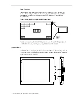
Страница 18: ...480 Figure 8 Pixel position of input data 480 line mode D640 DH480 D640 DH1 D1 DH480 D1 DH1 D2 DH1 D3 DH1 D1 DH2 D2 DH2 D1 DH3 R G B R L H U D L UP The display image may be rotated 180 degrees using the R L and U D signals present on J3 Refer to Inverting the Display on page 21 for more information Connectors The LC640 480 33 AC display has three connectors on the side of the display J3 is the vid...

Страница 19: ...und 2 CK Dot Clock 3 HSync Horiz Sync 4 VSync Vert Sync 5 GND Ground 6 R0 Red data LSB 7 R1 Red data 8 R2 Red data 9 R3 Red data 10 R4 Red data 11 R5 Red data MSB 12 GND Ground 13 G0 Green data LSB 14 G1 Green data 15 G2 Green data 16 G3 Green data 17 G4 Green data 18 G5 Green data MSB 19 GND Ground 20 B0 Blue data LSB 21 B1 Blue data 22 B2 Blue data 23 B3 Blue data 24 B4 Blue data 25 B5 Blue data...

Страница 20: ...gh side voltage source output 2 VRLUM Analog dimming input 3 GND Signal ground return 4 ABCOFF Automatic brightness control mode disable input 5 DISABL Backlight disable input Backlight Power Connector J1 Backlight power VH is applied via J1 which is a polarized 3 pin 3mm pitch header with gold plated 15µ contact surfaces and a release latch J1 is equivalent to a Molex 43650 0301 Micro Fit 3 0 ser...

Страница 21: ...black is 25 ms typical and the fall response time from black to white is 45 ms typical This is shown in Figure 11 Figure 11 Response Times τr Rise wht to blk 25 ms typ τf Fall blk to wht 45 ms typ white τr black white 100 90 10 0 Photo detector output Relative Value τf time Dimming Initial backlight dimming is performed by decreasing tube current allowing for substantially higher tube life in appl...

Страница 22: ...inance Biased ABC Rpot or Vin open Combination of dimming control and ambient light sensor sets display luminance In this mode VRLUM has twice the influence compared to the ambient light sensor hence VRLUM can drive luminance to either extreme regardless of ambient light conditions Ambient light influence max is capped at 3000 lux Dimming Control Interfacing An analog dimming control is available ...

Страница 23: ...ge provided by the source does not quite reach the 0 or 5 Vdc rails Method C shows a simple strap which sets the display to maximum luminance If the input is left unconnected the input will be in the mid level half luminance condition Method D represents a CMOS or TTL logic gate or a comparator to drive the backlight DISABL input Method E shows an open collector device such as a bipolar transistor...

Страница 24: ...e to the characteristics of the CCFL tubes Lamp luminance decreases at low temperatures as the mercury condenses out of the gas and it decreases again at high temperatures as the tube phosphors become less efficient The LC640 480 33 AC has been designed to provide peak luminance at normal room temperatures Backlight power consumption decreases as temperatures climb as the working voltage of the CC...

Страница 25: ... Figure 14 Warmup Curve Display Dimensions The recommended clearance shown in Figure 15 illustrates the distance behind the display ECA which should be left for free low of air for the purposes of convection cooling In Figure 15 dimensions are in millimeters Tolerances unless specified are as follows x 0 50 xx 0 25 Note The dimensions in this drawing are approximate Please contact Planar Applicati...

Страница 26: ...LC640 480 33 AC Operations Manual OM600 01 24 Figure 15 Display Dimensions ...

Страница 27: ...anty does not apply in cases of improper or inadequate maintenance by the Buyer unauthorized modification of the goods operation of the goods outside their environmental specifications neglect or abuse of the goods or modification or integration with other goods not covered by a Planar warranty when such modification or integration increases the likelihood of damage of the goods Ordering Informati...

Страница 28: ...Beaverton OR 97006 1992 Tel 1 503 690 1100 Fax 1 503 690 1493 sales planar com app_eng planar com Planar Systems Inc Olarinluoma 9 P O Box 46 FIN 02201 Espoo Finland Tel 358 9 42 0010 Fax 358 9 420 0200 intlsales planar com tech_support planar com Visit the Planar web site http www planar com OM600 01 ...

Отзывы: