background image

LC640.480.21-065 Operations Manual (OM610-00)

10

Signal Timing

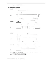
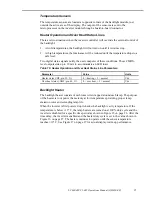
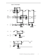
Video signal timing diagrams are shown in Figures 2 through 4 on the following pages.
Table 8 refers to these diagrams.

Table 8. Video Signal Timing.

Parameter

Symbol

Min.

Typ.

Max.

Unit

CLK

Frequency

1

1/tc

21.0

25.175

29.0

MHz

Duty

t ch/ t c

0.4

0.5

0.6

Rise, fall

t crf

10

ns

30.0

31.778

33.6

µ

s

Period

2

t h

800

CLK

Display period

t hd

640

CLK

Front-porch

t hf

2

16

CLK

Pulse width

t hp

10

96

CLK

t hb

5

48

CLK

Back-porch

*) t hp + t hb

64

144

CLK

CLK-Hsync timing

t hch

12

ns

Hsync-CLK timing

t hcx

8

ns

Hsync-Vsync timing

t vh

15

ns

Vsync-Hsync timing

t vs

15

ns

Hsync

Rise, fall

t hrf

10

ns

16.1

16.683

17.2

ms

Period

3

t v

525

H

Display period

t vd

480

H

Front-porch

t vf

1

12

H

Pulse width

t vp

2

2

H

t vb

4

31

H

Back-porch

*) t vp + t vb

6

33

H

Vsync

Rise, fall

10

ns

CLK-DATA timing

t ds

8

ns

DATA-CLK timing

t dh

12

ns

Rise, fall

t drf

10

ns

DATA

R0-R5

G0-G5

B0-B5

DE-CLK timing

t es

8

ns

CLK-DE timing

t eh

12

ns

DE

Rise, fall

t erf

10

ns

1

39.722 ns (Typ.)

2

31.468 kHz (Typ.)

3

59.94 Hz (Typ.)

Note

: Keep all parameters within the specified range. Do not operate the LCD

module without an input DE signal.

Содержание LC640.480.21-065

Страница 1: ...Operations Manual LC640 480 21 065 HIGH PERFORMANCE 6 5 COLOR TFT AMLCD The Definition of Quality ...

Страница 2: ...ColorBrite is a trademark of Planar Systems Inc This document is subject to change without notice Planar provides this information as reference only and does not imply any recommendation or endorsement of other vendor s products Revision Control Date Description September 2000 Document number OM610 00 ...

Страница 3: ...e 4 Mechanical Characteristics 5 Optical Characteristics 6 Viewing Angles 7 Response Times 7 Interfacing and Operation 8 Control Basics 8 Power Requirements 8 Power Sequencing LCD 9 Video Signals 9 Video Signal Characteristics 9 Signal Timing 10 Video Characteristics 14 Pixel Position 15 Warmup Characteristic 16 Connectors 17 Video Input and Backlight Control Connector J1 17 Backlight Inverter and...

Страница 4: ... Curve 16 Figure 9 Connector Locations 17 Figure 10 Dimming Voltage Input on J1 DIM 20 Figure 11 Luminance vs Dimming Voltage Manual Dimming 21 Figure 12 Luminance Levels Automatic Dimming Ambient Light Sensor 22 Figure 13 Luminance Levels Automatic Dimming Manual Offset 23 Figure 14 Backlight Power Consumption 24 Figure 15 Sensor Temperature vs Lamp Heater Inverter Startup Time Delay 26 Figure 16...

Страница 5: ...e heated at low temperatures to increase their luminance and extend their life Located in front of the backlight module are several diffusing and brightness enhancement films Inverter Module This assembly contains the backlight inverter electronics microprocessor heater control circuitry and input output connectors All the components are mounted to a single circuit board The microprocessor control...

Страница 6: ...f the display Thermal Control Several thermal sensors located on the backlight module allow the display to operate safely at temperature extremes At low ambient temperatures heaters on the backlight module warm the lamps to a safe temperature before energizing the lamps This cold start routine extends the life of the lamps and increases the luminance at low temperatures During the warm up period p...

Страница 7: ...present on the video interface unterminated video cable lengths of more than 12 inches 300 mm are discouraged Cleaning Care should be taken to minimize scratching Clean the display front with a dry soft cloth such as a professional photographic lens cleaner Disposable cleaning cloths are recommended to minimize the risk of inadvertently scratching the display with particles embedded in a re used c...

Страница 8: ...n operating 0 to 10k ft per IEC 68 2 13 0 to 40k ft per IEC 68 2 13 Vibration random Operating Non operating 0 02 g 2 Hz 5 500 Hz 30 min ea axis per IEC 68 2 34 Specific profiles for each axis SAE J1455 section 4 9 Shock Operating Non operating 100 g 6 ms half sine wave 3 shocks per surface per IEC 68 2 27 Safety and EMI Certifications The display will not inhibit the end product from compliance w...

Страница 9: ...wn in Table 3 are in millimeters inches Table 4 Mechanical Characteristics Display External Dimensions width height depth 178 8 7 04 nominal 126 8 4 99 nominal 38 3 1 51 nominal Weight normal 470 g 1 05 lbs Display Active Area width height diagonal 132 48 5 22 nominal 99 36 3 91 nominal 165 10 6 5 Pixel Pitch width height 207 0 008 nominal 207 0 008 nominal ...

Страница 10: ...ts is defined as follows Lnu 1 Lmin Lmax x 100 Luminance Control typical Dimming range 50 1 initial 300 1 stabilized Lmax after 15 minutes at max lum then Lmin at min lum dimming range Lmax Lmin Ambient Light Sensor Response Field of view Dynamic range Visible light filtered 420 to 675nm 50 pts 50 degrees typical to half sensitivity 0 to 3000 Lux typ assumes 18 scene reflectance Viewing Angles Hor...

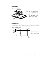
Страница 11: ... θ V Vertical angle 35 θ V Vertical angle 45 and R L and U D default Response Times As shown in Figure 2 the rise response time from white to black is 40 ms typical and the fall response time from black to white is 50 ms typical Figure 2 Response Times τr Rise wht to blk 40 ms typ τf Fall blk to wht 50 ms typ white τr black white 100 90 10 0 Photo detector output Relative Value τf time ...

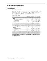
Страница 12: ... Min Typ Max Units Panel Panel voltage nominal 5 0V VCC 4 75 5 0 5 25 Vdc Absolute max VCC VCC 0 3 6 5 Vdc ICC VCC 5 0V ICC 470 640 mAdc Inverter Inverter voltage nominal 12 0V VINV 8 0 12 0 18 0 Vdc Absolute max voltage VINV 20 0 Vdc Current VINV 8 0V max luminance IINV 1 6 1 8 Adc Backlight Backlight heater voltage VLH 8 0 12 0 18 0 Vdc Backlight heater current ILH 2 0 3 0 Adc Cell heater voltag...

Страница 13: ...75 V 4 75 V 0 V 0 V 0 t 35 ms 0 t 35 ms ms t 150 1 The supply voltage for input signals should be the same as VCC 2 Apply VDD within the LCD operation period When the backlight turns on before LCD operation or the LCD operation turns off before the backlight turns off the display may momentarily become white 3 When the power is off please keep whole signals Hsync Vsync CLK DE and DATA low level or...

Страница 14: ...orch t hp t hb 64 144 CLK CLK Hsync timing t hch 12 ns Hsync CLK timing t hcx 8 ns Hsync Vsync timing t vh 15 ns Vsync Hsync timing t vs 15 ns Hsync Rise fall t hrf 10 ns 16 1 16 683 17 2 ms Period3 t v 525 H Display period t vd 480 H Front porch t vf 1 12 H Pulse width t vp 2 2 H t vb 4 31 H Back porch t vp t vb 6 33 H Vsync Rise fall 10 ns CLK DATA timing t ds 8 ns DATA CLK timing t dh 12 ns Ris...

Страница 15: ...e 4 Timing Diagram tc tch tcrf tcrf tds tdh INVALID INVALID DATA CLK VIH VIL 1 5 V VIH VIL 1 5 V VIH VIL 1 5 V R0 to R5 B0 to B5 G0 to G5 tdrf tdrf teh tes teh tes terf terf DE CLK 1 5 V thch thcs Hsync thrf VIH VIL 1 5 V 1 5 V VIH VIL 1 5 V tvh tvs tvrf ...

Страница 16: ...LC640 480 21 065 Operations Manual OM610 00 12 Figure 5 Timing Diagram ...

Страница 17: ...LC640 480 21 065 Operations Manual OM610 00 13 Figure 6 Timing Diagram Hsync ...

Страница 18: ...1 1 1 1 1 1 1 1 1 1 1 1 1 1 0 0 0 0 0 0 1 1 1 1 1 1 0 0 0 0 0 0 1 1 1 1 1 1 0 0 0 0 0 0 1 1 1 1 1 1 0 0 0 0 0 0 1 1 1 1 1 1 Red grayscale Black dark bright Red 0 0 0 0 0 0 0 0 0 0 0 1 0 0 0 0 1 0 1 1 1 1 0 1 1 1 1 1 1 0 1 1 1 1 1 1 0 0 0 0 0 0 0 0 0 0 0 0 0 0 0 0 0 0 0 0 0 0 0 0 0 0 0 0 0 0 0 0 0 0 0 0 0 0 0 0 0 0 0 0 0 0 0 0 0 0 0 0 0 0 0 0 0 0 0 0 0 0 0 0 0 0 0 0 0 0 0 0 Green grayscale Black da...

Страница 19: ...0 D 1 0 D X 0 D 638 0 D 639 0 D 0 1 D 1 1 D X 1 D 638 1 D 639 1 D 0 Y D 1 Y D X Y D 638 Y D 639 Y D 0 478 D 1 478 D X 478 D 638 478 D 639 478 D 0 479 D 1 479 D X 479 D 638 479 D 639 479 Reverse scan DPS H D 639 479 D 638 479 D X 479 D 1 479 D 0 479 D 639 478 D 638 478 D X 478 D 1 478 D 0 478 D 639 Y D 638 Y D X Y D 1 Y D 0 Y D 639 1 D 638 1 D X 1 D 1 1 D 0 1 D 639 0 D 638 0 D X 0 D 1 0 D 0 0 Figur...

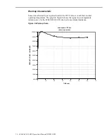
Страница 20: ... their normal operating temperature The graph in Figure 8 shows the typical room temperature warmup curve for the LC640 480 21 065 when set to maximum luminance Figure 8 Warmup Curve Luminance VS Time warm up curves 0 00 10 00 20 00 30 00 40 00 50 00 60 00 70 00 80 00 90 00 100 00 0 10 20 30 40 50 60 70 TIME min PERCENT OF MAX LUMINANCE ...

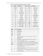
Страница 21: ...gure 9 Connector Locations Video Input and Backlight Control Connector J1 The video input and backlight control signals are connected to the display through a 40 pin dual row 1 27 mm pitch square pin locking connector Samtec FTSH 120 01 L DV EJ A The mating connector is available through Samtec as a cable assembly FFSD series Consult your Samtec representative 1 800 SAMTEC for cable and connector ...

Страница 22: ...or 38 TS1 Temperature sensor 39 HT Heater indicator 40 OHT Overtemp indicator Signal I O Description CLK I Video Clock HSync I Horizontal Sync Vsync I Vertical Sync R0 R5 I Red Data G0 G5 I Green Data B0 B5 I Blue Data GND I Ground Signal return for logic and power supplies Isolated from the display metal bezel DE I Data Enable DPS I Display Scan Low or open normal High image upside down VCC I AML...

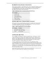
Страница 23: ...o diode anode 2 PDCATH Photo diode cathode 3 GND Power ground Tethering the Light Sensor The protruding circuit board area containing the light sensor is designed so it can be snapped off and removed from the main interface board Once the ambient sensor is removed it will require the addition of a cable between J3 and J8 in order to function With the cable installed the sensor can be remotely posi...

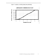
Страница 24: ... its position has no effect Manual Dimming This mode allows the user to adjust the luminance by varying the input from 0 to 5 Vdc on pin 33 DIM of the video input connector J1 See Figures 10 and 11 Table 15 Manual Dimming Specifications Description Specification Dimming range Approximately 300 1 Analog voltage input DIM Compatible with voltage and potentiometer 3 terminal No connection results in ...

Страница 25: ... 21 065 Operations Manual OM610 00 21 Figure 11 Luminance vs Dimming Voltage Manual Dimming LUMINANCE VS DIMMING VOLTAGE 0 00 20 00 40 00 60 00 80 00 100 00 0 1 2 3 4 5 6 DIMMING VOLTAGE PERCENT OF MAX LUMINANCE ...

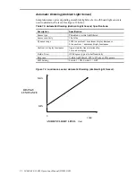
Страница 26: ... type Photodiode visible light filtered Sensor sensitivity 10 nA lux Dynamic range 3000 lux ambient maximum display luminance 0 lux ambient minimum display luminance Ambient to display luminance Approximately linear relationship 1 second averaging Field of view 50 degrees typical to half sensitivity Response Visible light filtered 420 to 675 nm 50 points SWI Setting Switch 1 ON Switch 2 OFF Figure...

Страница 27: ...ON Figure 13 Luminance Levels Automatic Dimming Manual Offset 4200 0 600 Min Max 1200 1800 2400 3000 3600 AMBIENT LIGHT LEVEL lux DISPLAY LUMINANCE DIM 4 5 Vdc DIM 4 0 Vdc DIM 3 5 Vdc DIM 3 0 Vdc DIM 2 5 Vdc DIM 2 0 Vdc DIM 1 5 Vdc DIM 1 0 Vdc DIM 0 5 Vdc Controlled Luminance Mode This function compensates for the luminance degradation of the lamps over time and constrains the maximum display lumi...

Страница 28: ...rates a cell heater to warm the AMLCD cell at cold temperatures Luminance Variation Due to Ambient Temperature Although the inverter features regulated lamp current drive luminance will vary across the temperature range due to the characteristics of the CCFL tubes Lamp luminance decreases at low temperatures as the mercury condenses out of the gas and it decreases again at high temperatures as the...

Страница 29: ...accommodate an LED load Table 19 Heater Operation and Over Heat Status Line Parameters Parameter Value Units Heater status HT pin 39 J1 0 heating 5 normal Vdc Over heat status OHT pin 40 J1 0 over heat 5 normal Vdc Backlight Heater The backlight heater consists of nichrome wire wrapped around each lamp The purpose of the heater is to vaporize the mercury at low temperatures providing proper lamp e...

Страница 30: ...d as shown in Figures 15 and 16 Inverter enable Inverter is enabled as shown in Figure 15 If the temperature is below 10 C inverter is turned off until the lamps are heated Status indicator Set the status indicator when the inverter is disabled See Heater Operation and Over Heat Status Lines On page 25 Hysteresis 3 0 C Heater voltage 8 18 Vdc Power 10 6 W 8 V 54W 18 V Figure 15 Sensor Temperature ...

Страница 31: ...10 20 30 40 50 60 70 80 90 100 110 50 40 30 20 10 0 10 20 30 40 50 SENSOR TEMPERATURE C LAMP HEATER DUTY CYCLE Cold Start Up Luminance VS Time 12 VDC w o cell heater full luminance display enclosed 0 00 10 00 20 00 30 00 40 00 50 00 60 00 70 00 80 00 90 00 100 00 0 00 2 00 4 00 6 00 8 00 10 00 12 00 14 00 16 00 18 00 20 00 22 00 Time min Luminance nits 40C ambient 20C ambient 0 C ambient ...

Страница 32: ...et as shown in Figure 20 on page 29 Table 21 Cell Heater Parameters Parameter Value Units Type Resistive ITO on glass 7 5 ohms square Total resistance 12 ohms None Active temperature sensor Monitor temperature sensor with the highest reading None Control Duty cycle is stepped as shown in Figure 21 Trip point Not applicable C Hysteresis 3 0 C Heater voltage 8 18 Vdc Power 5 3 8 V 27 18V Watts Figur...

Страница 33: ...Duty Cycle SENSOR TEMPERATURE VS MAXIMUM POWER TIME ITO CELL HEATER 1 0 1 2 3 4 5 6 50 40 30 20 10 0 10 20 30 40 50 SENSOR TEMPERATURE C MAXIMUM POWER TIME MIN SENSOR TEMPERATURE VS DUTY CYCLE ITO CELL HEATER 10 0 10 20 30 40 50 60 70 80 90 100 110 50 40 30 20 10 0 10 20 30 40 50 SENSOR TEMPERATURE C DUTY CYCLE ...

Страница 34: ...ature Control Parameters Parameter Value Units Active temperature sensor Monitor temperature sensor with the highest reading None Control Maximum duty cycle is stepped as shown in Figure 21 Hysteresis 3 0 C Figure 21 Temperature Control Maximum Pulse Width Modulation Duty Cycle SENSOR TEMPERATURE VS MAXIMUM PWM DUTY CYCLE 10 0 10 20 30 40 50 60 70 80 90 100 110 80 85 90 95 100 105 110 115 120 SENS...

Страница 35: ... between same color dot defects Quantity 8 each color5 Adjacent three or more dots 0 pair each color 1 F means full luminous dot s bright point independent from viewing angle H means half luminous dot s bright point dependent on viewing angle 2 Dark dots are counted while the screen is illuminated with Red Green or Blue dots only 3 Adjacency is considered separately for each color adjacency among ...

Страница 36: ... Average diameter D 0 5 mm 3 points Width 0 05 mm All allowed 0 05 mm Width 0 1 mm L 0 7 mm 0 7 mm L 1 0 mm 1 0 mm L All allowed 5 points 0 point 0 1 mm Width 0 point Other objects or dust between polarizer and glass Average diameter D 0 2 mm 0 2 mm D 0 3 mm 0 3 mm D 0 5 mm 0 5 mm D All allowed 11 points 4 points 0 points The distance between each defect is larger than 6 5 mm Figure 22 Diameter Ca...

Страница 37: ...odule that should be left to provide free flow of air for convection cooling In Figure 23 dimensions are in millimeters Figure 23 Display Dimensions Unless specified tolerances are x 0 50 xx 0 25 Note The dimensions in this drawing are approximate Please contact Planar Applications Engineering to request the actual drawing prior to beginning your design ...

Страница 38: ......
Страница 39: ...y the Buyer unauthorized modification of the goods operation of the goods outside their environmental specifications neglect or abuse of the goods or modification or integration with other goods not covered by a Planar warranty when such modification or integration increases the likelihood of damage of the goods Ordering Information Product Part Number Description LC640 480 21 065 996 0406 00 Stan...

Страница 40: ...Beaverton OR 97006 1992 Tel 1 503 690 1100 Fax 1 503 690 1493 sales planar com app_eng planar com Planar Systems Inc Olarinluoma 9 P O Box 46 FIN 02201 Espoo Finland Tel 358 9 42 0010 Fax 358 9 420 0200 intlsales planar com tech_support planar com Visit the Planar web site http www planar com OM610 00 ...

Отзывы: