background image

9

INSTALLATION INSTRUCTIONS 

STAND BASE INSTALLATION

The monitor is supplied complete with a stand.If you prefer to wall mount the monitor, 
please follow the instructions on page 21 to remove the stand. Be sure to include the stand 
with the monitor if it is necessary to return the unit.

CAUTION


Put the monitor on a stable surface.The monitor may cause injury or 
damage if it falls or is dropped.


Do not give a strong impact to the monitor.It may cause damage.


Unplug the monitor before removal or installation to avoid electric shock 
or damage.

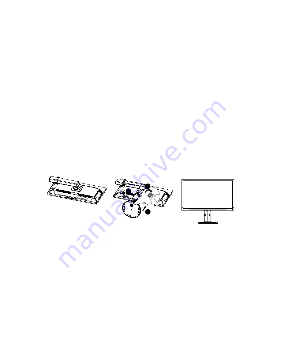
<Installation>

1.  Put a piece of soft cloth on the table beforehand to prevent the monitor from being 

scratched. Lay the monitor flat on a table with front face down. Turn the stand counter-
clockwise.

2.  Install the Stand-Base to the Monitor.
3.  Fix the monitor to the stand by using the screw. Once screw is securely fastened, push 

down the knob on the screw.

1

2

3

<Remove>

1.  Put a piece of soft cloth on the table beforehand to prevent the monitor from being  

scratched. Lay the monitor flat on a table with front face down.

2.  Pull up the knob of the screw, and remove the screw and the Stand-Base.

Содержание IX2851

Страница 1: ...IX2851 LED LCD Monitor...

Страница 2: ...ghts are reserved No part of this document may be reproduced translated to another language or stored in a retrieval system or transmitted by any means electronic mechanical photocopying recording or...

Страница 3: ...CTIONS 9 ADJUSTING THE VIEWING ANGLE 10 CONTROLS AND CONNECTORS 11 OPERATING INSTRUCTIONS 12 GENERAL INSTRUCTIONS 12 FRONT PANEL CONTROL 13 HOW TO ADJUST A SETTING 14 ADJUSTING THE PICTURE 15 PLUG AND...

Страница 4: ...e equipment off and on the user is encouraged to try to correct the interference by one or more of the following measures 1 Reorient or relocate the receiving antenna 2 Increase the separation between...

Страница 5: ...ors tension puis sous tension l utilisateur est invit essayer de corriger l interf rence par une ou plusieurs des mesures suivantes 1 R orienter ou d placer l antenne de r ception 2 Augmenter la dista...

Страница 6: ...home consult your dealer or local power company The monitor is equipped with a three pronged grounded plug a plug with a third grounding pin This plug will fit only into a grounded power outlet as a...

Страница 7: ...oniteur est quip d une prise de terre trois broches fiche standard avec une troisi me broche pour la terre Cette fiche ne peut tre ins r e que dans une prise reli e la terre comme dispositif de s curi...

Страница 8: ...shop where you purchased the product SPECIAL NOTES ON LCD MONITORS The following symptoms are normal with LCD monitor and do not indicate a problem NOTES Due to the nature of the fluorescent light th...

Страница 9: ...for Windows Recommended Resolutions 3840 2160 60Hz LED Backlight energy efficient Ergonomic Design Space Saving Compact Case Design PACKAGE LIST The product package should include the following items...

Страница 10: ...g the monitor before removal or installation to avoid electric shock or damage Installation 1 Put a piece of soft cloth on the table beforehand to prevent the monitor from being scratched Lay the moni...

Страница 11: ...ot topple the monitor when you change the monitor s angle You are able to adjust the monitor as below Tilt angle 5 23 Pivot angle 0 90 5 23 90 Swivel angle 160 160 Height adjustment 160 160 13cm NOTES...

Страница 12: ...either a wall power outlet or the power outlet socket on your PC depending on the type of power cord supplied with your LCD monitor SIGNAL CABLE Connecting the Signal Cable Plug one end of the signal...

Страница 13: ...monitor By changing these settings the picture can be adjusted to your personal preferences The power cord should be connected Connect the video cable from the monitor to the video card Press the pow...

Страница 14: ...locked except POWER button To lock the OSD press and hold the MENU button while the monitor is off and then Press power button to turn the monitor on To un lock the OSD press and hold the MENU button...

Страница 15: ...on is highlighted press the MENU button to activate it If the function selected has a sub menu press or again to navigate through the sub menu functions Once the desired function is highlighted press...

Страница 16: ...40 Contrast 50 Brightne ss Contrast Grayed Nonadjustable Game Brightness 60 Contrast 50 Brightness Contrast Grayed Nonadjustable Movie Brightness 80 Contrast 50 Brightness Contrast Grayed Nonadjustabl...

Страница 17: ...op Multi View function PIP Picture in Picture Mode PBP Picture by Picture Mode PIP Size Small Small sub window Middle Middle sub window Large Large sub window PIP Position Right Up Choose top right po...

Страница 18: ...ng a time out period will automatically switch to an OFF mode This reduces the monitor s internal power supply consumption After the video input signal is restored full power is restored and the displ...

Страница 19: ...spect monitor s video cable and make sure none of the pins are bent Make sure computer is operational by hitting the CAPS LOCK key on the keyboard while observing the CAPS LOCK LED The LED should eith...

Страница 20: ...pixel clock signal With a wrong phase adjustment the picture has horizontal disturbances in light picture ERROR MESSAGE POSSIBLE SOLUTION NO SIGNAL 1 Check that the signal cable is properly connected...

Страница 21: ...Pin D Sub DVI 24 Pin Dual link DVI D HDMI HDMI DisplayPort DisplayPort Audio Audio in 1 x stereo audio in for PC audio jack 3 5 Speaker 3W x 2 Power Power Supply 100 240V 50 60Hz Consumption Max 105W...

Страница 22: ...879 60 317 800 600 72Hz 48 077 72 188 800 600 75Hz 46 875 75 000 Mac Mode 832 624 75Hz 49 725 74 550 XGA 1024 768 60Hz 48 363 60 004 1024 768 70Hz 56 476 70 069 1024 768 75Hz 60 023 75 029 SXGA 1280x...

Страница 23: ...1 15 15 Pin Color Display Signal Cable PIN NO DESCRIPTION PIN NO DESCRIPTION 1 Red 9 5V 2 Green 10 Detect Cable 3 Blue 11 Ground 4 Ground 12 DDC Serial Data 5 Ground 13 H Sync 6 R Ground 14 V Sync 7 G...

Страница 24: ...4 ML Lane 2 n Lane 2 5 GND Ground 6 ML Lane 2 p Lane 2 7 ML Lane 1 n Lane 1 8 GND Ground 9 ML Lane 1 p Lane 1 p 10 ML Lane 0 n Lane 0 11 GND Ground 12 ML Lane 0 p Lane 0 13 GND Ground 14 GND Ground 1...

Страница 25: ...0 Shield 18 5V Power max 50mA 9 TMDS Data 0 19 Hot Plug Detect 10 TMDS Clock PIN NO DESCRIPTION PIN NO DESCRIPTION 1 TMDS Data 2 13 TMDS Data 3 2 TMDS Data 2 14 5V Power 3 TMDS Data 2 4 Shield 15 Gro...

Страница 26: ...disconnect the power cord 2 Lay the LCD display face down on a towel or blanket 3 Remove the four screws attaching the base Screw dimension M4 x 14mm 4 Attach the mounting bracket from the VESA compa...

Страница 27: ...r at http www planar com support for product registration operations manuals touch screen drivers warranty information and access to Planar s Technical Library for online troubleshooting To speak with...

Страница 28: ...Q41G28M193501A 04 16...

Отзывы: