


1.4 USE INSTRUCTIONS
After correct installation has been carried out following these instructions, the sensor
can be supplied with power supply.
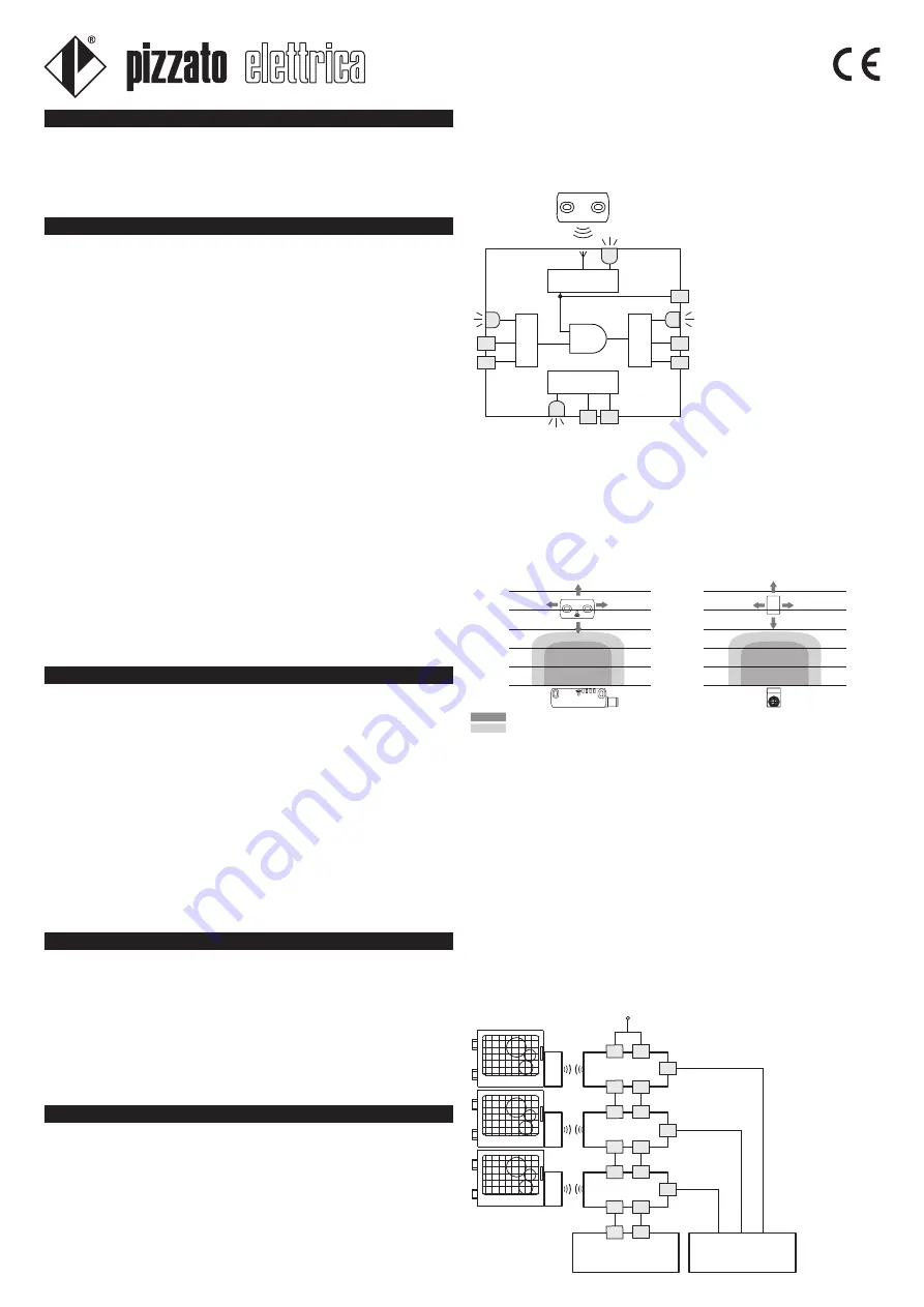
The diagram below represents the four logic functions that interact within the sensor.
In the initial “POWER ON” state, the f0 function of the sensor carries out an internal
self-diagnosis which, if successfully completed, brings the device to the “RUN” state. If
the test is not passed due to an internal fault, the sensor enters the “ERROR” state.
The “RUN” state refers to normal operation: the function f1 evaluates the state of the
IS1 and IS2 inputs and simultaneously the f2 checks the presence of the actuator in
the safe activation area.
When these two conditions occur, the f3 function activates the OS1 and OS2 safety
outputs.
Warning during and after the installation:
• The installation must be performed by qualified staff only.
• The sensor is supplied as univocally combined with the actuator found in the
packing.
• The sensor and the other connected safety devices must be powered from a single
PELV or SELV type source having safe insulation and conforming to the relevant
standards.
• It is recommended to supply the safety sensor using a source separate from the
machinery source.
• Before switching on the device, check that the power supply is correct.
• Before installation and at regular intervals, check the right outputs switching and the
system operation of the sensor and the associated safety module.
• Do not use the sensor as a mechanical stop.
• Verify the assured operating (s
ao
) and release distances (s
ar
).
• It is advisable to make adjustment observing the diagram reported in the switching
distances section.
• Do not use a hammer to carry out adjustments.
• Do not install the sensor and the actuator on strong magnetic field.
• The safety category for the system including the sensor also depends on the external
devices and their connection.
• For applications using low working frequency, it is necessary to carry out an
operational test once a year.
Shock, vibrations and wear:
• Do avoid impact with the sensor. Excessive shock and vibrations could not guarantee
the right working of the sensor.
• The actuator must not strike sensor.
• In case of damages or wear is necessary to change the whole device, included the
actuator
(for non programmable versions).
Warning during the wiring:
• Keep the load under the value given in the utilization category.
• Turn off the power supply before accessing the sensor connection contacts
.
• Before handling the product, discharge any static electricity by touching a metallic
mass connected to earth. Electrostatic discharges (ESD) could damage the sensor.
• The M12 connector must only be connected and disconnected with the power supply
switched off.
The sensors use RFID technology for safe control of the guards present in industrial
machinery.
The said sensors have no mechanical contacts, therefore can guarantee long working
life for systems subject to frequent opening/closing manoeuvres and operating in
hostile environmental conditions.
Moreover, they provide a high level of protection against tampering, thanks to the
univocal code transmitted by the actuator.
1 INTRODUCTION
1.1 WARNING
• The sensor can be used as a safety device (EN 60204) associated with a mobile
guard and respective safety module, according to EN 60947-5-3 / A1 standards.
• The sensor can be used as a component in a safety category with 4 / PL e system
according to the EN ISO 13849-1 standard, and with SIL CL 3 integrity level accord
-
ing to the EN 62061 standard.
• Use the device by following its instructions, observing its operation limits and using
it according to the safety standards in force.
• The utilization conformed to the final use, implies the respect of standards in force
regarding the installation and the operation, in detail: EN 60947-5-3 / A1, EN
13849-1, EN 62061, EN 60204-1, EN 1088, EN ISO 12100-1, EN ISO 12100-2.
• The manufacturer responsibility is excluded in case of:
- Utilization not according to final destination
- Not observing of the safety instructions
- Installation and reparations not performed by qualified and authorized staff.
- Omission of functional tests
• In following applications please beforehand contact Support (point 2)
- In nuclear power plants, trains, air crafts, cars, incinerators, medical devices or in
any applications where the safety of two or more persons depends on the right
operation of the device.
- Applications which are not contemplated in the instructions sheet.
1.2 UTILIZATION LIMITS
Sensor states:
OFF: the sensor is switched off, not powered.
POWER ON: state immediately following switching on, when the sensor carries out
internal tests.
RUN: state of the sensor in normal operation.
ERROR: safety state in which the outputs are deactivated. Indicates the presence of
a fault inside the sensor, a short circuit between the safety outputs (OS1 and OS2), a
short circuit between a safety output and the ground or a short circuit between a safety
output and the power supply. To come out of this state, it is necessary to restart the
sensor.
PROGRAMMING: programming state in which the outputs are deactivated. This state
is contemplated for programmable versions only.
1.3 DEFINITIONS
The sensor inputs are not only monitored for their state but also for their coherence:
the inputs are normally activated in a simultaneous way. In the case where only one
of the two inputs is deactivated, the sensor deactivates the safety outputs and signals
a non-coherent input condition by making the IN LED green/orange light blink. Both
inputs must be deactivated, and then reactivated for the safety inputs to become ac
-
tive again.
During the RUN state, the f0 function carries out cyclical internal tests in order to show
up any fault. When any internal error
is detected, the sensor is brought to
the “ERROR” state (PWR LED with
red fixed light) causing the safety out
-
puts to be immediately deactivated.
The “ERROR” state can also be
reached in case of short circuits oc-
curring between the safety outputs
(OS1 and OS2) or a short circuit of
an output occurring towards ground
or towards supply voltage.
Also in this case, the f3 function de
-
activates the safety outputs and the
error state is signalled by the OUT
LED red light blinking.
The O3 signalling output is activated
during the “RUN” state in correspond-
ence with the actuator being detected
within the activation area, independ-
ently from the IS1 and IS2 input state.
The state of this output is displayed
by the LED ACT.
Switching distances
When the actuator is brought inside the safe activation zone (dark grey area), the sen
-
sor enables the outputs (LED OUT and LED ACT on, green).
When the actuator leaves the safe zone, the sensor keeps the outputs enabled; how
-
ever, by means of the LED ACT (blinking, orange/green), it indicates that the actuator
is entering the limit activation zone (light grey area).
When the actuator leaves the limit activation zone, the sensor disables the outputs and
switches off the LED OUT and LED ACT.
WARNING!
Device’s actuation/release distances may be affected by the presence of conductive
or magnetic material close to the sensor. Actuation and release distances must be
verified after installation.
25
20
15
10
5
0
25
20
15
10
5
0
-15 -10 -5 0 5 10 15
-15 -10 -5 0 5 10 15
Legend:
Activation distance s
n
(mm)
Deactivation distance s
nr
(mm)
Note: The drawing of the activation areas is indicative.
Connecting with safety modules
It is possible for several sensors to be installed in cascade connection up to a maxi
-
mum number of 32 units, while maintaining the safety category 4 / PL e according to
the EN ISO 13849-1 standard, and the SIL CL 3 integrity level according to the EN
62061 standard. Verify that the PFH and MTTFd value of the system, composed of
sensors chain and safety module, complies with the SIL/PL level requested by the
application.
With this connection method, the following instructions must be observed:
• Connect the inputs of the first sensor in the chain to the power supply.
• The outputs of the last sensor in the chain must be evaluated by means of a safety
module.
• Use a sensor cascade only with the safety modules specified.
• Respect the positioning distances between the sensors.
• Respect the limits on the stray capacity of the output lines, specified in the electrical
characteristics.
• Check that the cascade response time respects the requirements of the safety func
-
tion to be obtained.
• The chain response time must be calculated while keeping into account that the
response time following the actuator being moved away is different from the response
time following the inputs being deactivated. If for example, looking at the following
diagram, we assume that the first guard of the chain is to open, then the total response
time of the ST series sensors will be at its maximum value: 150 ms + 12 ms + 12 ms
= 174 ms.
ST D•••0MK
ST D•••0MK
ST D•••0MK
CS
PLC
OS1
OS2
IS1
IS2
IS1
IS2
OS1
OS2
IS1
IS2
OS1
OS2
O3
SM D1T
SM D1T
SM D1T
O3
O3
+Vcc
f2
f1
f3
f0
OS1
OS2
IS2
IS1
IN
O3
PWR
A2
A1
ACT
OUT
© 2012 Copyright Pizzato Elettrica - original instructions
ZE_FOG84D12-IE
36063 MAROSTICA (VI) ITALY
Via Torino, 1
Phone +39.0424.470.930
Fax +39.0424.470.955
E-mail [email protected]
www.pizzato.com


