6
SitG Electricity User Guide ROI V1017
Series Circuit
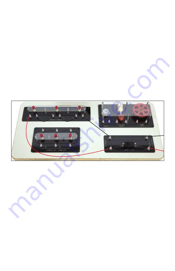
1. Using a red lead, connect the (+) terminal of the power out side
of the power switch area to the (+) terminal on the left side of the
series circuit area.
2. Using a black lead, connect the (-) terminal of the power out side
of the power switch area to the (-) terminal on the right side of the
series circuit area.
3. Turn the power switch on to observe that the circuit is not yet
complete. The lights will not turn on.
4. Turn the switch off to continue making connections for the circuit.
5. Using two additional leads (color does not matter), finish making
the circuit connections as shown in Figure 5.
Parallel Circuit
1. Using a red lead, connect the (+) terminal of the power out side of
the power switch area to the (+) terminal on the right side of the
parallel circuit area.
2. Using a black lead, connect the (-) terminal of the power out side
of the power switch area to the (-) terminal on the right side of the
parallel circuit area.
3. Turn the power switch on to observe that the first light comes on,
but the other two lights do not.
4. Turn the power switch off to continue connecting the circuit.
5. Use leads (black for the (-) terminals, red for the (+) terminals) to
connect the other two lights within the parallel circuit area as
shown in Figure 6.
Figure 5


