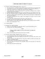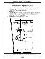
4-58.FIBERGLASS FRACTURE AND PATCH REPAIRS.
a.
Remove wax, oil and dirt from around damaged area with acetone, methylethylketone or equivalent.
b. Using a key hole saw, electric saber saw, or sharp knife cut away ragged edges. Cut back to sound
material.
c.
Remove paint three inches back from around damaged area.
d. Working inside the structure, bevel the edges to approximately a 30 degree angle and rough-sand the
hole and the area around it, using 80-grit dry paper. Feather back for about two inches all around the
hole. This roughens the surface for strong bond with patch.
e.
Cover a piece of cardboard or metal with cellophane. Tape it to the outside of the structure covering
the hole completely. The cellophane should face toward the inside of the structure. lf the repair is on a
sharp contour or shaped area, a sheet of aluminum formed to a similar contour may be placed over the
area. The aluminum should also be covered with cellophane.
f.
Prepare a patch of fiberglass mat and cloth to cover an area two inches larger than the hole.
g. Mix a small amount of resin and catalyst, enough to be used for one step at a time, according to kit
instructions.
h. Thoroughly wet mat and cloth with catalyzed resin. Daub resin on mat first, and then on cloth. Mat
should be applied against structures surface with cloth on top. Both pieces may be wet out on
cellophane and applied as a sandwich. Enough fiberglass cloth and mat reinforcements should be used
to at least replace the amount of reinforcements removed in order to maintain the original strength. lf
damage occurred as a stress crack, an extra layer or two of cloth may be used to strengthen area.
i.
Lay patch over hole on inside of structure, cover with cellophane, and squeegee from center to edges
to remove all air bubbles and assure adhesion around edge of hole. Air bubbles will show white in the
patch and they should all be worked out to the edge. Remove excess resin before it gels on the part.
Allow patch to cure completely.
j.
Remove cardboard or aluminum sheet from outside of hole and rough-sand the patch and edge of hole.
Feather edge of hole about two inches into undamaged area.
k. Mask area around hole with tape and paper to protect surface. Cut piece of fiberglass mat about one
inch larger than the hole and one or more pieces of fiberglass cloth two inches larger than the hole.
Brush catalyzed resin over hole, lay mat over hole and wet out with catalyzed resin. Use a daubing
action with brush. Then apply additional layer or layers of fiberglass cloth to build up patch to the
surface of structure. Wet out each layer thoroughly with resin.
1. With a squeegee or broad knife, work out all air bubbles in the patch. Work from center to edge,
pressing patch firmly against the structure. Allow patch to cure for 15 to 20 minutes.
m. As soon as patch begins to set up, but while still rubbery, take a sharp knife and cut away extra cloth
and mat. Cut on outside edge of feathering. Strip cut edges of structure. Do this before cure is
complete, to save extra sanding. Allow patch to cure overnight.
n. Using dry 80 grit sandpaper on a power sander or sanding block, smooth patch and blend with
surrounding surface. Should air pockets appear while sanding, puncture and fill with catalyzed resin. A
hypodermic needle may be used to fill cavities. Let cure and resand.
o. Mix catalyzed resin and work into patch with fingers. Smooth carefully and work into any crevices.
p. Cover with cellophane and squeegee smooth. Allow to cure completely before removing cellophane.
Let cure and resand.
q. Brush or spray a coat of catalyzed resin to seal patch. Sand patch, finish by priming, again sanding and
applying color coat.
NOTE
Brush and hands may be cleaned in solvents such as acetone or
methylethylketone. lf solvents are not available, a strong solution of
detergent and water may be used.
Revised: 10/18/83
1E18
* CHEROKEE ARROW III SERVICE MANUAL
STRUCTURES
Содержание ARROW III
Страница 4: ...THIS PAGE INTENTIONALLY LEFT BLANK 1A4...
Страница 12: ...THIS PAGE INTENTIONALLY LEFT BLANK 1A12...
Страница 93: ...Figure 4 1 Aileron and Flap Installation Issued 12 15 76 1D21 CHEROKEE ARROW III SERVICE MANUAL STRUCTURES...
Страница 94: ...Figure 4 2 Wing Installation Revised 2 13 89 1D22 CHEROKEE ARROW III SERVICE MANUAL STRUCTURES...
Страница 95: ...Figure 4 2 Wing Installation cont Revised 11 21 80 1D23 CHEROKEE ARROW III SERVICE MANUAL STRUCTURES...
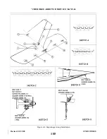
Страница 101: ...Figure 4 4 Empennage Group Installation Revised 11 21 80 1E5 CHEROKEE ARROW III SERVICE MANUAL STRUCTURES...
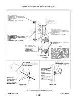
Страница 102: ...Figure 4 4 Empennage Group Installation cont Revised 11 21 80 1E6 CHEROKEE ARROW III SERVICE MANUAL STRUCTURES...
Страница 104: ...Figure 4 5 Windshield Installation Typical Issued 12 15 76 1E8 CHEROKEE ARROW III SERVICE MANUAL STRUCTURES...
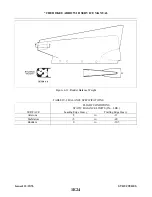
Страница 107: ...Figure 4 7 Skin Materials and Thickness Issued 12 15 76 1E11 CHEROKEE ARROW III SERVICE MANUAL STRUCTURES...
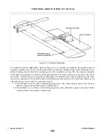
Страница 117: ...Figure 4 9 Control Surface Balance Tool Issued 12 15 76 1E21 CHEROKEE ARROW III SERVICE MANUAL STRUCTURES...
Страница 124: ...Figure 4 15 Identification of Aircraft Fluid Lines Added 5 1 80 1F4 CHEROKEE ARROW III SERVICE MANUAL STRUCTURES...
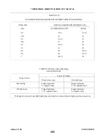
Страница 130: ...TABLE V ll CABLE TENSION VS AMBIENT TEMPERATURE Revised 2 13 89 1F10 CHEROKEE ARROW III SERVICE MANUAL SURFACE CONTROLS...
Страница 131: ...Figure 5 1 Control Column Assembly Revised 5 1 80 1F11 CHEROKEE ARROW III SERVICE MANUAL SURFACE CONTROLS...
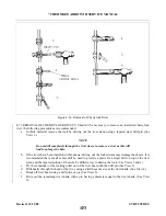
Страница 132: ...Figure 5 la Method of Installing Rod End Bearings Added 12 11 78 1F12 CHEROKEE ARROW III SERVICE MANUAL SURFACE CONTROLS...
Страница 135: ...Figure 5 2 Aileron Controls Revised 11 21 80 1F15 CHEROKEE ARROW III SERVICE MANUAL SURFACE CONTROLS...
Страница 142: ...Figure 5 6 Stabilator Controls Revised 5 1 80 1F22 CHEROKEE ARROW III SERVICE MANUAL SURFACE CONTROLS...
Страница 147: ...Figure 5 8 Stabilator Trim Control Issued 12 15 76 1G3 CHEROKEE ARROW III SERVICE MANUAL SURFACE CONTROLS...
Страница 149: ...Figure 5 9 Rudder and Steering Pedal Assembly Issued 12 15 76 1G5 CHEROKEE ARROW III SERVICE MANUAL SURFACE CONTROLS...
Страница 151: ...Figure 5 10 Rudder Controls Revised 12 11 78 1G7 CHEROKEE ARROW III SERVICE MANUAL SURFACE CONTROLS...
Страница 157: ...Figure 5 15 Flap Controls Interim Revision 2 21 95 1G13 CHEROKEE ARROW III SERVICE MANUAL SURFACE CONTROLS...
Страница 162: ...Figure 5 20 Fabricated Stabilator Rigging Tool Issued 12 15 76 1G18 CHEROKEE ARROW III SERVICE MANUAL SURFACE CONTROLS...
Страница 163: ...Figure 5 21 Fabricated Rudder Rigging Tool Issued 12 15 76 1G19 CHEROKEE ARROW III SERVICE MANUAL SURFACE CONTROLS...
Страница 171: ...lH3 INTENTIONALLY LEFT BLANK...
Страница 172: ...lH4 INTENTIONALLY LEFT BLANK...
Страница 178: ...Figure 6 2 Hydraulic System Installation Revised 2 13 89 1H10 CHEROKEE ARROW III SERVICE MANUAL HYDRAULIC SYSTEM...
Страница 188: ...THIS PAGE INTENTIONALLY LEFT BLANK Revised 2 13 89 1H20 CHEROKEE ARROW III SERVICE MANUAL HYDRAULIC SYSTEM...
Страница 190: ...Figure 6 6 Gear Back up Extender Actuator Revised 2 13 89 1H22 CHEROKEE ARROW III SERVICE MANUAL HYDRAULIC SYSTEM...
Страница 195: ...Figure 6 7 Nose Gear Actuating Cylinder Revised 2 13 89 1I3 CHEROKEE ARROW III SERVICE MANUAL HYDRAULIC SYSTEM...
Страница 198: ...Figure 6 9 Main Gear Actuating Cylinder Revised 2 13 89 1I6 CHEROKEE ARROW III SERVICE MANUAL HYDRAULIC SYSTEM...
Страница 212: ...GRIDS lI20 AND lI21 INTENTIONALLY LEFT BLANK Revised 2 13 89 1I20 CHEROKEE ARROW III SERVICE MANUAL HYDRAULIC SYSTEM...
Страница 234: ...Figure 7 11 Aligning Main Gear Revised 2 13 89 1J19 CHEROKEE ARROW III SERVICE MANUAL LANDING GEAR AND BRAKE SYSTEM...
Страница 254: ...Figure 7 19 Removal of Anchor Bolt Revised 2 13 89 1K15 CHEROKEE ARROW III SERVICE MANUAL LANDING GEAR AND BRAKE SYSTEM...
Страница 259: ...Figure 7 23 Toe Brake Installation Revised 2 13 89 1K20 CHEROKEE ARROW III SERVICE MANUAL LANDING GEAR AND BRAKE SYSTEM...
Страница 264: ...Figure 7 26 Bleeding Brakes Revised 2 13 89 1L1 CHEROKEE ARROW III SERVICE MANUAL LANDING GEAR AND BRAKE SYSTEM...
Страница 286: ...THIS PAGE INTENTIONALLY LEFT BLANK Revised 2 13 89 2A8...
Страница 292: ...Figure 8 3 Propeller Installation Revised 8 31 77 2A14 CHEROKEE ARROW III SERVICE MANUAL POWER PLANT CONTINENTAL...
Страница 298: ...Figure 8 6 Engine Installation Revised 12 11 78 2A20 CHEROKEE ARROW III SERVICE MANUAL POWER PLANT CONTINENTAL...
Страница 323: ...Figure 8 28 Ignition Schematic Revised 8 31 77 2B21 CHEROKEE ARROW III SERVICE MANUAL POWER PLANT CONTINENTAL...
Страница 330: ...Figure 8 33 Engine Controls Revised 8 31 77 2C4 CHEROKEE ARROW III SERVICE MANUAL POWER PLANT CONTINENTAL...
Страница 347: ...Figure 8A 1 Propeller Installation Hartzell Revised 5 1 80 2C21 CHEROKEE ARROW III SERVICE MANUAL POWER PLANT LYCOMING...
Страница 354: ...Figure 8A4 Engine Installation PA 28R 201 Revised 10 18 83 2D4 CHEROKEE ARROW III SERVICE MANUAL POWER PLANT LYCOMING...
Страница 385: ...Figure 9 1 Fuel System Diagram PA 28R 201 Issued 12 15 76 2E11 CHEROKEE ARROW III SERVICE MANUAL FUEL SYSTEM...
Страница 387: ...Figure 9 2 Fuel System Diagram PA 28R 201T Revised 2 13 89 2E13 CHEROKEE ARROW III SERVICE MANUAL FUEL SYSTEM...
Страница 389: ...Figure 9 3 Fuel Sender Units Installation Revised 2 13 89 2E15 CHEROKEE ARROW III SERVICE MANUAL FUEL SYSTEM...
Страница 409: ...Figure 10 1 Instrument Panel Typical Revised 2 13 89 2F11 CHEROKEE ARROW III SERVICE MANUAL INSTRUMENTS...
Страница 412: ...Figure 10 2 Pitot Static System Revised 2 13 89 2F14 CHEROKEE ARROW III SERVICE MANUAL INSTRUMENTS...
Страница 414: ...Figure 10 3 Vacuum Auxiliary Vacuum Installation Revised 2 13 89 2F16 CHEROKEE ARROW III SERVICE MANUAL INSTRUMENTS...
Страница 482: ...Figure 11 44b Ignition Switch Revised 2 13 89 2I12 CHEROKEE ARROW III SERVICE MANUAL ELECTRICAL SYSTEM...
Страница 483: ...Figure 11 45 Terminal Block Revised 2 13 89 2I13 CHEROKEE ARROW III SERVICE MANUAL ELECTRICAL SYSTEM...
Страница 498: ...TABLE XI VI ELECTRICAL SYMBOLS Revised 2 13 89 2J4 CHEROKEE ARROW III SERVICE MANUAL ELECTRICAL SYSTEM...
Страница 506: ...Figure 11 62 Instrument Lights PA 28R 201T Revised 2 13 89 2J12 CHEROKEE ARROW III SERVICE MANUAL ELECTRICAL SYSTEM...
Страница 507: ...Figure 11 63 Alternator and Starter PA 28R 201 Revised 2 13 89 2J13 CHEROKEE ARROW III SERVICE MANUAL ELECTRICAL SYSTEM...
Страница 510: ...Figure 11 65 Fuel Pump PA 28R 201T Revised 2 13 89 2J16 CHEROKEE ARROW III SERVICE MANUAL ELECTRICAL SYSTEM...
Страница 511: ...Figure 11 66 Landing Gear PA 28R 201 201T Revised 2 13 89 2J17 CHEROKEE ARROW III SERVICE MANUAL ELECTRICAL SYSTEM...
Страница 528: ...INTENTIONALLY LEFT BLANK 2K10 THRU 2L24 2K10...
Страница 542: ...Figure 14 4 Manifold Set Operation Revised 2 13 89 3A14 CHEROKEE ARROW III SERVICE MANUAL ACCESSORIES AND UTILITIES...
Страница 578: ...Figure 14 16 Fixed Oxygen System Revised 2 13 89 3C2 CHEROKEE ARROW III SERVICE MANUAL ACCESSORIES AND UTILITIES...
Страница 580: ...Figure 14 18 Oxygen Tubing Installation Revised 2 13 89 3C4 CHEROKEE ARROW III SERVICE MANUAL ACCESSORIES AND UTILITIES...
Страница 594: ...INTENTIONALLY LEFT BLANK 3C18 THRU 3L24...

