1. Install the lines with as few bends as possible. Care must be taken not to damage
the couplings or kink the tubing. Use clean hard drawn copper tubing where no
appreciable amount of bending around obstruction is necessary, if soft copper must
be used, care must be taken to avoid sharp bends which may cause a restriction.
2. The lines should be installed so that they will not obstruct service access to the coil,
air handling system or filter.
3.8 PRECAUTIONS DURING LINE INSTALLATION
9
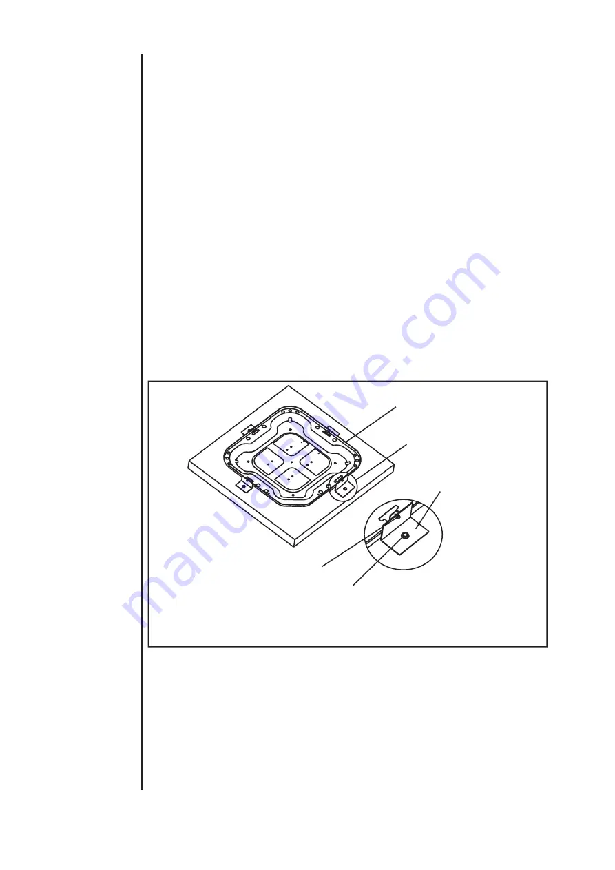
3.7 FACTORY-PREFERRED TIE-DOWN METHOD
Step 3: Using field supplied L-shaped bracket to locate holes on concrete and drill pilot
holes which is at least 1/4” deeper than fastener being used.
IMPORTANT
Self drilling screws to base pan should not exceed 3/8” long to avoid damaging
coil.
Step 4: Using conventional practices to install brackets, tighten concrete fasteners and
self-tapping screws (See Fig.6).
NOTE
NOTE: 1. One bracket for each side. For extra stability, 2 brackets for each side.
2. Do not over-tighten the concrete fastener to avoid weakening the concrete.
Step 1: Prior to installing clear pad of debris.
IMPORTANT
Then cement pad must meet local codes and must be the proper thickness to
accommodate fasteners.
Step 2: Center and level unit onto pad.
IMPORTANT NOTE:
These instructions are intended to provide a method to tie-down system to cement slab
as a securing procedure for high wind areas. It is recommended to check Local Codes
for tie-down methods and protocols.
REQUIRED PARTS LIST
SEE DETAIL B
#7 X 3/8” Self Tapping Screws
(Don’t Exceed 3/8” long)
1/4”
Χ
1-1/2” Hex Washer Head Concrete Screws
(3/16” Pilot Hole Needed. Pilot Hole Should Be1/4” Deeper
Than The Fastener Embedment)
Fig.6 PREFERRED TIE-DOWN METHOD
DETAIL B
Brackets:
2” width, 1/16” thickness,
height as required.
Available from distributor
or in market place.
The dimension see FIG.2


