55
VSX-D710S
•
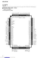
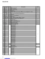
Pin Function
No.
Pin Name
I/O
Pin Function
Active
1
G2
O
Grid output 2
H
2
G1
O
Grid output 1
H
3
NC
−
Connect to VDD
4
ACIN
I
AC pulse input
5
RDS_DT
I
Serial control DATA signal of RDS communication
6
RDS_CK
I
Serial control CLOCK signal of RDS communication
7
DIRLOCK
I
ERR/OVER input from CODEC
8
RMC
I
Remote control signal input (no-carrier signal)
9
VER_2
I
Destination switch 2
10
PLL_CE
O
Chip select signal for communication with LC72131 (tuner)
H
11
CDC_CS
O
CODEC chip serect
12
CDC_CK
O
CODEC, TC9164 control clock
13
CDC_DO
O
CODEC, TC9164 control data output
14
CDC_DI
I
Data input from CODEC
15
STEREO
I
Stereo/Monoral signal judgment signal
16
TUNED
I
TUNED information
17
ENC_A
I
EVOL Rotary encoder signal input A
18
ENC_B
I
EVOL Rotary encoder signal input B
19
AMUTE
O
Audio mute
L
20
CSB
O
Chip select for control of YSS912 sub DSP
L
21
DSP_CS
O
Chip select for control of YSS912 main DSP
L
22
DSP_CK
O
Clock signal for communication with YSS912
H
23
DSP_SI
I
DATA input signal for communication with YSS912
24
DSP_SO
O
DATA output signal for communication with YSS912
H
25
MVRATT
O
ATT control of master volume (L : Less than -15dB)
H
26
ST_EVR
O
Strobe signal for communication with electric volume IC
H
27
PLL_DO
I
Data input signal for communication with LC72131 (tuner)
28
AVref
−
Connect to VDD
29
KEYIN1
I
Key input A/D conversion port 1
30
KEYIN2
I
Key input A/D conversion port 2
31
KEYIN3
I
Key input A/D conversion port 3
32
VER_1
I
Destination switch (A/D input)
33
FENC_A
I
FUNC Rotary encoder signal input A
34
FENC_B
I
FUNC Rotary encoder signal input B
35
AMP_DC
I
DC abnormality detection of protection circuit (L : Abnormality detection) *1
L
36
AMP_OL
I
Over-load detection of protection circuit (L : Abnormality detection) *2
L
37
AVSS
−
Connect to VSS
38
RST
−
Reset
39
EXTAL
−
Connect to the oscillator (7.2MHz)
40
XTAL
−
41
VSS
−
Connect to VSS
42
TX
−
Open
43
TEX
−
Connect to VSS
44
VDD
−
+5V
45
VFDP
−
-30V
46
VIDEO1
O
NJM2296D control
H
47
VIDEO2
48
VIDEO3
49
SYS_DT
O
Data signal for communication with M62446, TC9163, TC9164 and PLL
H
O
Clock signal for communication with M62446, TC9163, TC9164 and PLL
H
50
SYS_CK
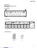
*1 : When DC voltage was output from amplifier, "POWER OFF" is displayed at FL display.
*2 : When the output of amplifier became overload state, "OVER LOAD" is displayed at FL display.
Содержание VSX-D710S
Страница 7: ...7 VSX D710S This page was intentionally left blank ...
Страница 17: ...VSX D710S 17 A B C D 5 6 7 8 5 6 7 8 A1 3 3 3 A ...
Страница 23: ...VSX D710S 23 A B C D 1 2 3 4 1 2 3 4 H P ASSY XWZ3356 I DIGITAL IN ASSY XWZ3361 J CN1501 A 2 3 403 K J I ...
Страница 31: ...VSX D710S 31 A B C D 5 6 7 8 5 6 7 8 J4 D J5 D 851 C Q51 IC52 IC51 AC IN NEUTRAL LIVE J2 G J1 G CN801 E B ...
Страница 34: ...VSX D710S 34 A B C D 1 2 3 4 1 2 3 4 A D D INPUT ASSY A IC1801 IC101 ...
Страница 35: ...VSX D710S 35 A B C D 5 6 7 8 5 6 7 8 A C1801 XNP3037 A SIDE B ...
Страница 37: ...VSX D710S 37 A B C D 5 6 7 8 5 6 7 8 CN102 A CN103 A R ENCODER ASSY L XNP3035 B SIDE A L K ...

