47
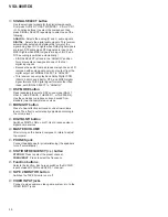
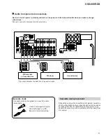
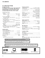
VSX-808RDS
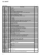
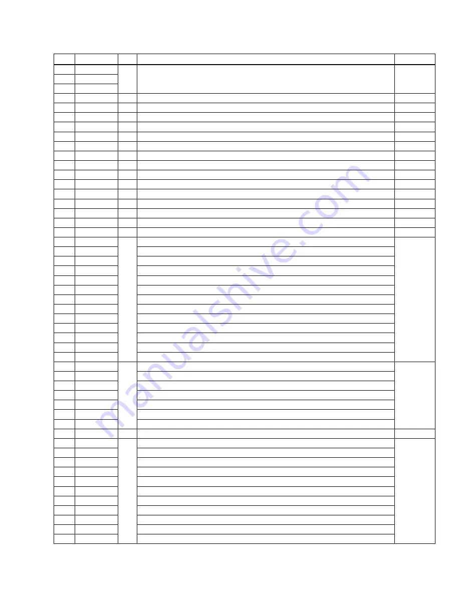
Note :• In the power off condition (with the remote control unit key or the main unit tact key), set to "L" excepting tuner mute (pin 54). However, it
nothing is done against to the input port.
• When pin 10 and 11 detect "L" at the reset, be careful because it enter the microcomputer's own test mode.
No.
Pin Name
I/O
Pin Function
Active
51
SVIDEO1
O
TC4051 control (S terminal control)
H
52
SVIDEO2
53
SVIDEO3
54
TMUTE
O
Tuner mute
H
55
VMUTE
O
Video mute
L
56
Not used
O
Open
57
LC4966
O
Input switch the DVD 6ch
H
58
ST_9174
O
Strobe signal for communication with TC9174
H
59
Not used
O
Open
60
Not used
O
Open
61
Not used
O
Open
62
RY_AC
O
AC relay ON/OFF
H
63
RY_HP
O
Headphone relay ON/OFF
H
64
RY_C/R
O
Rear/Center relay ON/OFF
H
65
RY_A+B
O
Speaker A + B relay ON/OFF
H
66
RY_B
O
Speaker B relay ON/OFF
H
67
RY_A
O
Speaker A relay ON/OFF
H
68
VHVL
O
Power switch for AMP system (H : VH)
H
69
S22/KEY13
O
Segment output 22/key scan output 13
H
70
S21/KEY12
Segment output 21/key scan output 12
71
S20/KEY11
Segment output 20/key scan output 11
72
S19/KEY10
Segment output 19/key scan output 10
73
S18/KEY9
Segment output 18/key scan output 9
74
S17/KEY8
Segment output 17/key scan output 8
75
S16/KEY7
Segment output 16/key scan output 7
76
S15/KEY6
Segment output 15/key scan output 6
77
S14/KEY5
Segment output 14/key scan output 5
78
S13/KEY4
Segment output 13/key scan output 4
79
S12/KEY3
Segment output 12/key scan output 3
80
S11/KEY2
Segment output 11/key scan output 2
81
S10/KEY1
Segment output 10/key scan output 1
82
S9
O
Segment output 9
H
83
S8
Segment output 8
84
S7
Segment output 7
85
S6
Segment output 6
86
S5
Segment output 5
87
S4
Segment output 4
88
S3
Segment output 3
89
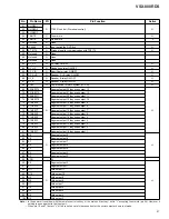
VDD
−
5V
90
S2
O
Segment output 2
H
91
S1
Segment output 1
92
G11
Grid output 11
93
G10
Grid output 10
94
G9
Grid output 9
95
G8
Grid output 8
96
G7
Grid output 7
97
G6
Grid output 6
98
G5
Grid output 5
99
G4
Grid output 4
100
G3
Grid output 3
Содержание VSX-808RDS
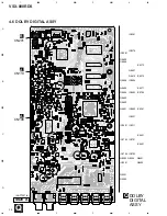
Страница 20: ...VSX 808RDS 20 A B C D 1 2 3 4 1 2 3 4 C9121 R9103 0 3 3 Q CN108 1 2 A 3 8 DOLBY DIGITAL ASSY 1 3 1 3 Q ...
Страница 22: ...VSX 808RDS 22 A B C D 1 2 3 4 1 2 3 4 1 3 Q 1 3 Q 3 9 DOLBY DIGITAL ASSY 2 3 2 3 Q ...
Страница 23: ...VSX 808RDS 23 A B C D 5 6 7 8 5 6 7 8 2 3 DOLBY DIGITAL ASSY 2 3 AWX7374 Q DSP MEMORY BLOCK 2 3 Q ...
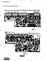
Страница 28: ...VSX 808RDS 28 A B C D 1 2 3 4 1 2 3 4 IC109 IC307 IC309 INPUT ASSY A SIDE B A ...
Страница 29: ...VSX 808RDS 29 A B C D 5 6 7 8 5 6 7 8 ANP7273 A 07 IC309 IC301 IC303 IC304 IC306 IC310 SIDE B A ...
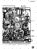
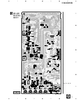
Страница 37: ...VSX 808RDS 37 A B C D 1 2 3 4 1 2 3 4 DOLBY DIGITAL ASSY Q SIDE B ANP7297 B IC9151 IC9101 Q ...
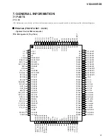
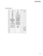
Страница 49: ...49 VSX 808RDS Anode Connection ...

