47
Connecting your equipment
03
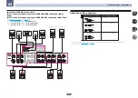
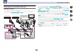
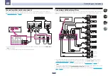
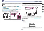
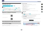
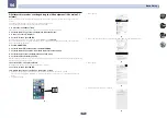
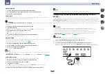
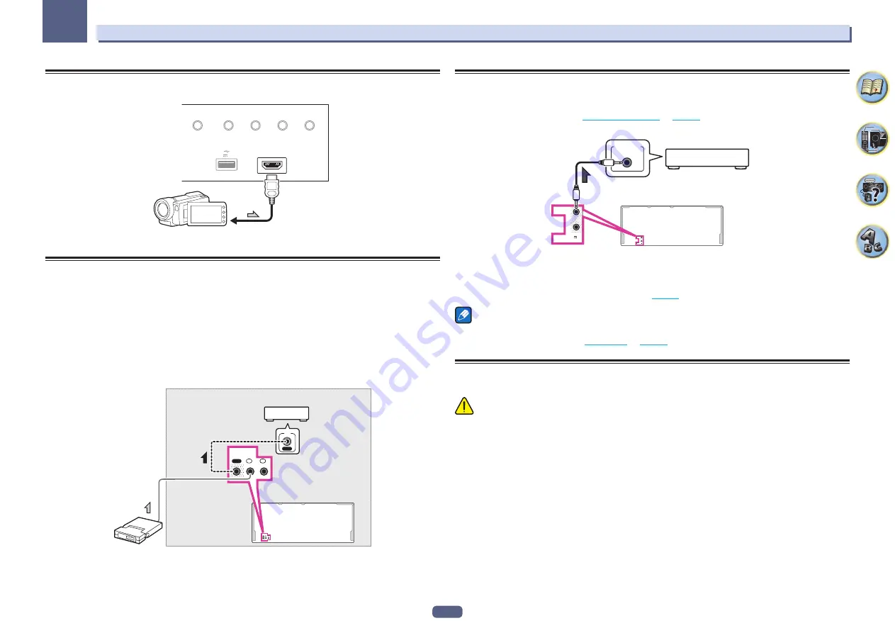
Connecting an HDMI-equipped component to the front panel
input
HDMI 5 INPUT
AUTO/ALC/
DIRECT
STATUS
BAND
TUNER EDIT
iPod iPhone
DIRECT CONTROL
5V 1 A
Video camera (etc.)
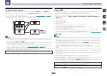
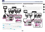
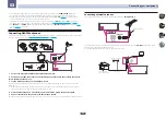
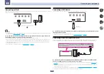
Connecting an IR receiver
If you keep your stereo components in a closed cabinet or shelving unit, or you wish to use the sub zone remote
control in another zone, you can use an optional IR receiver (such as a Niles or Xantech unit) to control your
system instead of the remote sensor on the front panel of this receiver.
!
Remote operation may not be possible if direct light from a strong fluorescent lamp is shining on the IR
receiver remote sensor window.
!
Note that other manufacturers may not use the IR terminology. Refer to the manual that came with your com-
ponent to check for IR compatibility.
!
If using two remote controls (at the same time), the IR receiver’s remote sensor takes priority over the remote
sensor on the front panel.
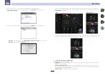
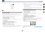
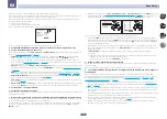
1 Connect the IR receiver sensor to the IR IN jack on the rear of this receiver.
IN
2
IN
HDMI OUT
OUT
1
2
IR
1
IN
OUT
IN 1
IN 2
IR
IN
IR
Closet or shelving unit
Non-Pioneer
component
IR receiver
2 Connect the IR IN jack of another component to the IR OUT jack on the rear of this receiver
to link it to the IR receiver.
Please see the manual supplied with your IR receiver for the type of cable necessary for the connection.
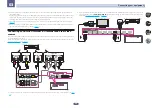
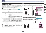
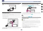
Switching components on and off using the 12 volt trigger
You can connect components in your system (such as a screen or projector) to this receiver so that they switch
on or off using 12 volt triggers when you select an input function. However, you must specify which input func-
tions switch on the trigger using the
on
. Note that this will only work with com-
ponents that have a standby mode.
(OUTPUT 12 V
TOTAL 150 mA MAX)
1
2
12V
TRIGGER
(OUTPUT 12 V
TOTAL 150 mA MAX)
1
2
12V
TRIGGER
12V TRIGGER
INPUT
%
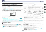
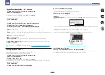
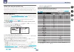
Connect the 12 V TRIGGER jack of this receiver to the 12 V trigger of another component.
Use a cable with a mono mini-plug on each end for the connection.
After you’ve specified the input functions that will switch on the trigger, you’ll be able to switch the component on
or off just by pressing the input function(s) you’ve set on
.
Note
The 12V trigger can be associated not only with switching of the input function but also with switching of the
HDMI OUT
terminal. For details, see
Plugging in the receiver
Only plug in after you have connected all your components to this receiver, including the speakers.
CAUTION
!
Handle the power cord by the plug part. Do not pull out the plug by tugging the cord, and never touch the
power cord when your hands are wet, as this could cause a short circuit or electric shock. Do not place the
unit, a piece of furniture, or other object on the power cord or pinch the cord in any other way. Never make a
knot in the cord or tie it with other cables. The power cords should be routed so that they are not likely to be
stepped on. A damaged power cord can cause a fire or give you an electric shock. Check the power cord once
in a while. If you find it damaged, ask your nearest Pioneer authorized independent service company for a
replacement.
!
Do not use any power cord other than the one supplied with this unit.
!
Do not use the supplied power cord for any purpose other than that described below.
!
The receiver should be disconnected by removing the mains plug from the wall socket when not in regular use,
e.g., when on vacation.
!
Make sure the blue
u
STANDBY/ON
light has gone out before unplugging.
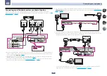
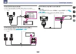
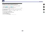
1 Plug the supplied power cord into the AC IN socket on the back of the receiver.
2 Plug the other end into a power outlet.

