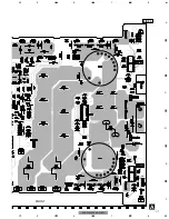
background image

5

5

6

7

8

F

E

D

C

B

A

5

6

7

8

PRS-D3000SPL/X1H/EW

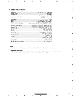
1. SPECIFICATIONS

Power source........................................................................................ 14.4 V DC (10.8 — 15.1 V allowable)
Grounding system .................................................................................................................. Negative type
Backup current ............................................................................................................................ 3 mA or less
Current consumption ................................................................................ 42 A (at continuous power, 4

)

Average current drawn* .................................................................................... 8.3 A (4 

for one channel)

........................................................................................................................9.0 A (2 

for one channel)

Fuse (external)  ........................................................................................................................................ 100 A
Dimensions  .................................................................................................. 300 (W) x 64 (H) x 279 (D) mm
Weight  .............................................................................................. 5.9 kg (Leads for wiring not included)
Maximum power output  .................................................................... 1,000 W x 1 (4

) / 2,000 W x 1 (2

)

Continuous power output (EW)...................... 800 W x 1 (4

) / 1,400 W x 1 (2

) (DIN45324, +B=14.4 V)

Continuous power output (UC) .................................... 500 W x 1 (at 14.4 V, 4 

, 20 —240 Hz 1.0% THD)

................................................................................1,000 W x 1 (at 14.4 V, 2 

, 20 —240 Hz 2.0% THD)

Load impedance ................................................................ 4 

(2 — 8 

allowable), (Ex. Bridge 4 — 16 

)

Frequency response  .......................................................................................... 10 — 240 Hz (+0 dB, –1 dB)
S/N ratio  ...................................................................................................................... 90 dB (IEC-A network)
Distortion .................................................................................................................... 0.05 % (50 W, 100 Hz)
Low pass filter  ............................................................................................ Cut off frequency: 40 — 240 Hz

............................................................................................................................Cut off slope: –24 dB/oct

Subsonic filter (HPF)  .......................................................................................................... Frequency: 20 Hz

..............................................................................................................................................Slope: –18 dB

Bass boost ............................................................................................................................ Level: 0 — 12 dB

............................................................................................................................ Frequency: 40 — 120 Hz

Phase control  ...................................................................................................................... SYNC, SYNC INV
Gain control  .......................................................................................................................... 200 mV — 6.5 V
Maximum input level / impedance .................................................................................. RCA: 6.5 V / 22 k

Note:

• Specifications and the design are subject to possible modification without notice due to improvements.

*Average current drawn

• The average current drawn is nearly the maximum current drawn by this unit when an audio signal is input.

Use this value when working out total current drawn by multiple power amplifiers.

Содержание PRS-D3000SPL/X1H/EW

Страница 1: ...aven 1087 Keetberglaan 1 9120 Melsele Belgium PIONEER ELECTRONICS ASIACENTRE PTE LTD 253 Alexandra Road 04 01 Singapore 159936 C PIONEER CORPORATION 2005 K ZZB FEB 2005 Printed in Japan ORDER NO CRT3421 CLASS D MONO AMPLIFIER PRS D3000SPL X1H EW Service Manual PRS D3000SPL X1H EW For details refer to Important check points for good servicing PRS D3000SPL X1H UC ...

Страница 2: ...test equipment and tools and have been trained to properly and safely repair complex products such as those covered by this manual Improperly performed repairs can adversely affect the safety and reliability of the product and may void the warranty If you are not qualified to perform the repair of this product properly and safely you should not risk trying to do so and refer the repair to a qualif...

Страница 3: ...side the product Please check that neither solder debris nor screws remain inside the product 8 There should be no semi broken wires scratches melting etc on the coating of the power cord Damaged power cords may lead to fire accidents so please be sure that there are no damages If you find a damaged power cord please exchange it with a suitable one 9 There should be no spark traces or similar mark...

Страница 4: ...EWS AND PARTS LIST 6 2 1 PACKING 6 2 2 EXTERIOR 8 3 SCHEMATIC DIAGRAM 10 3 1 SCHEMATIC DIAGRAM GUIDE PAGE 10 4 PCB CONNECTION DIAGRAM 16 4 1 AMP UNIT 16 5 ELECTRICAL PARTS LIST 20 6 ADJUSTMENT 24 7 GENERAL INFORMATION 25 7 1 DIAGNOSIS 25 7 1 1 DISASSEMBLY 25 7 1 2 CONNECTOR FUNCTION DESCRIPTION 26 8 OPERATIONS 27 ...

Страница 5: ... Hz 1 0 THD 1 000 W x 1 at 14 4 V 2 Ω 20 240 Hz 2 0 THD Load impedance 4 Ω 2 8 Ω allowable Ex Bridge 4 16 Ω Frequency response 10 240 Hz 0 dB 1 dB S N ratio 90 dB IEC A network Distortion 0 05 50 W 100 Hz Low pass filter Cut off frequency 40 240 Hz Cut off slope 24 dB oct Subsonic filter HPF Frequency 20 Hz Slope 18 dB Bass boost Level 0 12 dB Frequency 40 120 Hz Phase control SYNC SYNC INV Gain c...

Страница 6: ... Spare Parts List The mark found on some component parts indicates the importance of the safety factor of the part Therefore when replacing be sure to use parts of identical designation Screws adjacent to mark on the product are used for disassembly For the applying amount of lubricants or glue follow the instructions in this manual In the case of no amount instructions apply as you think it appro...

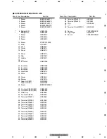
Страница 7: ...EG0011 3 Lock Tie HNV0071 4 Polyethylene Bag HEG0022 5 Contain Box HHL0449 6 Carton EW HHG0453 Carton UC HHG0449 7 Protector HHP0269 8 Screw BYC40P180FZK 9 1 Warranty Card EW HRY1157 9 2 Owner s Manual EW HRD0243 Owner s Manual UC HRD0242 10 Fuse Holder Unit HXC1937 11 Install Card HRP1298 12 Fuse 100A HEK1292 13 Fuse Holder HKR1026 14 Cover HNS0112 15 Caution Card HRP1299 16 Cushion Wrap HNM8415 ...

Страница 8: ...40 39 32 33 17 14 13 21 41 46 46 51 31 29 30 26 20 20 20 20 20 26 26 26 26 11 11 11 11 11 11 11 7 16 16 16 16 7 4 4 3 4 1 1 3 3 3 3 3 2 2 5 5 5 10 4 4 2 2 49 49 25 15 4 4 48 19 22 8 1 1 1 1 8 8 8 8 8 10 10 12 8 1 2 3 4 1 2 3 4 F E D C B A PRS D3000SPL X1H EW 2 2 EXTERIOR ...

Страница 9: ...6 Spacer HNV0016 27 Amp Unit EW HWH0220 Amp Unit UC HWH1298 28 Screw BBZ30P060SAD 29 Cushion CN303 EW CNM6825 30 Cushion CN304 EW CNM6825 31 Cord Assy HDE0065 32 Pin Jack CN801 HKB0004 33 Terminal CN301 HKE0069 34 Terminal CN903 HKE1050 35 Terminal CN601 HKF0001 36 Terminal CN602 HKF0001 37 Terminal CN603 HKF0001 38 Terminal CN604 HKF0001 39 Terminal CN605 HKF0001 40 Terminal CN607 HKF0001 41 Term...

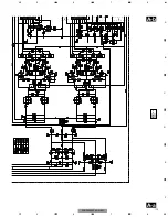
Страница 10: ...am Guide page Detailed page Note When ordering service parts be sure to refer to EXPLODED VIEWS AND PARTS LIST or ELECTRICAL PARTS LIST A a A 10 1 2 3 4 1 2 3 4 F E D C B A PRS D3000SPL X1H EW 3 SCHEMATIC DIAGRAM 3 1 SCHEMATIC DIAGRAM GUIDE PAGE ...

Страница 11: ...2 The mark found on some component parts indicates the importance of the safety factor of the part Therefore when replacing be sure to use parts of identical designation Symbol indicates a resistor No differentiation is made between chip resistors and discrete resistors NOTE Symbol indicates a capacitor No differentiation is made between chip capacitors and discrete capacitors ...

Страница 12: ...12 1 2 3 4 1 2 3 4 F E D C B A PRS D3000SPL X1H EW A a A b A a A a A b 1 2 3 4 5 ...

Страница 13: ...13 5 6 7 8 F E D C B A 5 6 7 8 PRS D3000SPL X1H EW A a A b A a A a A b 6 7 8 ...

Страница 14: ...14 1 2 3 4 1 2 3 4 F E D C B A PRS D3000SPL X1H EW A a A b A b 1 2 3 4 5 A AMP UNIT ...

Страница 15: ...2 The mark found on some component parts indicates the importance of the safety factor of the part Therefore when replacing be sure to use parts of identical designation Symbol indicates a resistor No differentiation is made between chip resistors and discrete resistors NOTE Symbol indicates a capacitor No differentiation is made between chip capacitors and discrete capacitors ...

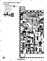
Страница 16: ...unted on this PCB include all necessary parts for several destination For further information for respective destinations be sure to check with the schematic dia gram 2 Viewpoint of PCB diagrams 1 2 3 4 5 6 9 10 11 12 Lch Rch SYNC INPUT SYNC OUTPUT SUB SONIC FILTER SWITCH MODE SELECT SWITCH 16 1 2 3 4 1 2 3 4 F E D C B A PRS D3000SPL X1H EW ...

Страница 17: ...17 5 6 7 8 F E D C B A 5 6 7 8 PRS D3000SPL X1H EW A SIDE A BFC SWITCH FRONT ...

Страница 18: ...18 1 2 3 4 1 2 3 4 F E D C B A PRS D3000SPL X1H EW A A AMP UNIT ...

Страница 19: ...19 5 6 7 8 F E D C B A 5 6 7 8 PRS D3000SPL X1H EW A SIDE B 1 ...

Страница 20: ...233 215 FET IRF2807 Q 619 A 182 215 FET IRF2807 Q 620 A 200 215 FET IRF2807 Q 623 A 220 23 FET IRF2807 Q 624 A 238 23 FET IRF2807 Q 625 A 187 23 FET IRF2807 Q 626 A 205 23 FET IRF2807 Q 628 B 205 99 Transistor KSC1623 Q 629 B 180 115 Transistor DTA114EK Q 630 B 186 122 Transistor DTC114TK Q 631 B 205 105 Transistor DTC114TK Q 632 B 209 122 Transistor KSC1623 Q 661 A 268 22 Transistor 2SA1048 Q 700...

Страница 21: ...8 30 Fuse 0 375A HEK0042 FU 702 A 88 36 Fuse 0 375A HEK0042 FU 801 B 8 91 Fuse 3A HEK0043 RESISTORS R 101 B 42 106 RS1 16S432J R 102 B 38 126 RS1 16S432J R 103 B 20 119 RS1 16S432J R 105 B 30 129 RS1 16S432J R 107 B 26 114 RS1 16S432J R 108 B 50 65 RS1 16S222J R 110 B 44 64 RS1 16S182J R 111 B 44 52 RS1 16S822J R 112 B 42 57 RS1 16S221J R 113 B 38 64 RS1 16S222J R 114 B 32 64 RS1 16S560J R 115 B 3...

Страница 22: ...182 RD1 4PU104J R 665 A 248 193 RD1 4PU512J R 667 B 140 125 RS1 16S563J R 668 A 257 24 RD1 4PU104J R 669 A 257 28 RD1 4PU472J R 670 B 249 160 RS1 16S222J R 671 B 186 105 RS1 16S272J R 672 B 256 179 RS1 16S242J R 673 B 153 125 RS1 16S563J R 674 B 142 125 RS1 16S103J R 675 B 153 120 RS1 16S563J R 676 B 140 120 RS1 16S563J R 677 B 142 120 RS1 16S103J R 678 B 202 129 RS1 16S103J R 679 B 134 125 RS1 16...

Страница 23: ...HCH0028 C 364 A 79 127 CQMA472J50 C 365 A 126 126 CQMA472J50 C 366 A 102 107 CEAT220M50 C 370 A 84 154 CEAT101M25 C 371 A 84 163 CEAT101M25 C 600 B 267 115 CKSRYB104K25 C 601 B 268 150 CKSRYB223K50 C 602 A 124 91 CFTNA103J50 C 603 B 202 114 CKSRYB103K50 C 604 A 189 141 CEAT100M50 C 605 B 202 116 CKSRYB223K50 C 606 A 198 136 CEAT100M50 C 607 B 202 120 CKSRYB223K50 C 609 B 202 112 CKSRYB223K50 C 610...

Страница 24: ...103J50 C 811 A 34 79 CFTNA103J50 C 812 A 24 111 CQMA472J50 C 813 B 24 84 CKSRYB471K50 C 814 A 34 89 CEAT100M50 C 815 B 41 85 CKSRYB272K50 C 816 B 46 77 CKSRYB272K50 C 817 A 52 139 CFTNA103J50 C 818 A 34 102 CFTNA103J50 C 819 A 23 79 CFTNA104J50 C 820 B 36 58 CKSRYB272K50 C 822 A 24 50 CEAT100M50 C 823 B 14 90 CKSRYB332K50 C 824 B 14 93 CKSRYB332K50 C 826 A 23 129 CFTNA103J50 C 830 B 14 95 CKSRYB33...

Страница 25: ...Case 2 Remove the two screws 3 Remove the two screws and then remove the Panel 2 Remove the four screws 3 3 3 3 2 2 2 2 Amp Unit 3 3 3 3 Remove the seven screws and then remove the Case 6 6 7 7 7 7 7 7 7 7 7 1 1 3 3 7 7 7 7 7 5 5 7 2 2 1 4 4 4 Remove the two screws 5 Remove the two screws and then remove the Panel 6 Remove the fourteen screws 7 Remove the fifteen screws and then remove the Amp Uni...

Страница 26: ...26 1 2 3 4 1 2 3 4 F E D C B A PRS D3000SPL X1H EW 7 1 2 CONNECTOR FUNCTION DESCRIPTION PRS D3000SPL X1H EW ...

Страница 27: ... For synced amplifier s gain control see the Setting the Gain for Synced Amplifier section MODE SELECT Switch You can select amplifier s sync mode from MAS TER SYNC and SYNC INV For the position of the MODE SELECT switch see the Connecting the Speaker Wires section Bass Boost Level Control Bass boost level control can boost the level around the frequency selected by the bass boost frequency contro...

Отзывы: