Pioneer PL-530, Руководство по обслуживанию
Pioneer PL-530 - высококачественный проигрыватель винила с автоматическим функциями, который воспроизводит звук высокого качества. Для правильной настройки устройства, загрузите операционное руководство с инструкциями на manualshive.com. Получите полезную информацию о настройке и обслуживании вашего проигрывателя бесплатно.
Поделиться
Скачать


Отзывы:
Нет отзывов
Похожие инструкции для PL-530
301
Бренд: Garrard Страницы: 33
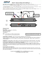
P
Бренд: iHold Music Страницы: 2
T35
Бренд: Harman Kardon Страницы: 9
T3
Бренд: JB Systems Страницы: 26
210
Бренд: Garrard Страницы: 8
Encore
Бренд: QuVIS Страницы: 152
RM Series
Бренд: Galaxy Audio Страницы: 12
T20
Бренд: Harman Kardon Страницы: 8

W602
Бренд: Magnavox Страницы: 18

Piccolo
Бренд: I.A.V. Страницы: 13
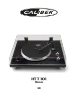
HTT 101
Бренд: Caliber Страницы: 16
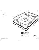
ALVA TT
Бренд: Cambridge Audio Страницы: 13
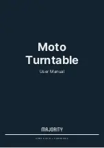
Moto
Бренд: MAJORITY Страницы: 104
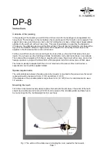
DP-8
Бренд: H. H. MORCH Страницы: 10
T30C
Бренд: Harman Kardon Страницы: 9

ST-8
Бренд: Harmon/Kardon Страницы: 9
DX300
Бренд: iBasso Audio Страницы: 64
Rabco ST5
Бренд: Harman Kardon Страницы: 8


