57
XC-IS21T
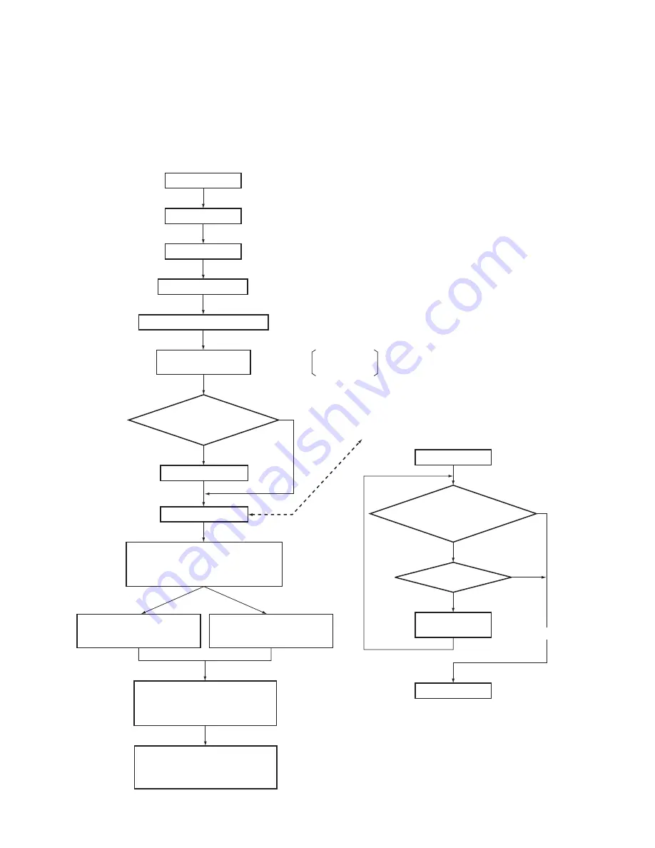
7.1.1 SEQUNCE AFTER THE POWER ON
Standby states
P35 SYSPOWER : "H"
P4 LCD POWER ON : "H"
P53 LCDRST : "L" RESET
Starts the LCD communication (
∗
2)
The condition that MUTE
is not released.
• VOLUME : 0
• DECK Function : excepting PLAY
Microcomputer
DECK Initialize Sequence
P11 : "H"
No
No
No
Yes
Yes
Check P79 MODE SW
input is "L".
Retry it to two times.
IC2601(BU4094) P12 is "H"
IC2601(BU4094) P11 is "L"
Yes
Transfer
P28 VOLDATA
P34 VOLCLK
P75 EXPCE
System bus communication (
∗
1)
Transfer the system POWER ON.
Note 1 : IC No. or P
∗∗
without name indicate the pin No.
of microcomputer.
Note ;
∗
1 : System bus communication
P29 SYSCLK
P46 SYSDATA
P47 SYSREQ
∗
2 : Starts the LCD communication
P48 LCDCLK
P49 LCDCE
P50 LCDDATA
∗
3 : Transfer the Function, Volume, BASS
and TREBLE data to the volume IC.
P27 VOLCE
P28 VOLDATA
P34 VOLCLK
∗
4 : Initial setting of CD decoder IC
P17 CDCLK
P18 CDLAT
P19 CDDATA
∗
5 : Initialize the TUNER PLL IC
P65 TXCE
P66 TXODAT
P67 TXCLK
P68 TXIDAT
Does the DECK Head down ?
(Is the MODE SW OFF ?)
MOTOR ON
MOTOR OFF
500 msec.
solenoid is ON ?
POWER ON
Power is ON.
Transmit the bus data.
Close the CD door.
Initialize the DECK.
Function : CD (
∗
4)
Initial setting of CD decoder IC.
P22 CDCONT : "L"
Initialize the LCD microcomputer.
DECK control IC starts
the data transfer.
Does CD door open ?
Is P9 and P10 at "H" level ?
Perform the following process after
one second after the POWER ON.
Transfer the Function, Volume, BASS
and TREBLE data to the volume IC. (
∗
3)
Perform the following process after
3.9 seconds after the POWER ON.
Release the system MUTE.
P71 SYSMUTE : "H"
Perform the following process after
4.0 seconds after the POWER ON.
Release the speaker relay.
P70 SPCONT : "H"
Is three times ?
Function : TUNER (
∗
5)
Initialize the TUNER PLL IC.
P64 TXPOW : "H"
7. GENERAL INFORMATION
7.1 DIAGNOSIS


