background image

PIONEER CORPORATION

4-1, Meguro 1-Chome, Meguro-ku, Tokyo 153-8654, Japan 

PIONEER ELECTRONICS (USA) INC.

P.O.Box 1760, Long Beach, CA 90801-1760 U.S.A.

PIONEER EUROPE NV

Haven 1087 Keetberglaan 1, 9120 Melsele, Belgium 

PIONEER ELECTRONICS ASIACENTRE PTE.LTD.

253 Alexandra Road, #04-01, Singapore 159936

PIONEER CORPORATION 2002

K-ZZD. DEC. 2002 Printed in Japan

ORDER NO.

CRT2991

BRIDGEABLE POWER AMPLIFIER

Service
Manual

GM-X572/XR/UC

GM-X572

XR/UC,XR/EW,XR/ES

For details, refer to "Important symbols for good services". 

Содержание GM-X572/XR/ES

Страница 1: ...EUROPE NV Haven 1087 Keetberglaan 1 9120 Melsele Belgium PIONEER ELECTRONICS ASIACENTRE PTE LTD 253 Alexandra Road 04 01 Singapore 159936 C PIONEER CORPORATION 2002 K ZZD DEC 2002 Printed in Japan ORDER NO CRT2991 BRIDGEABLE POWER AMPLIFIER Service Manual GM X572 XR UC GM X572XR UC XR EW XR ES For details refer to Important symbols for good services ...

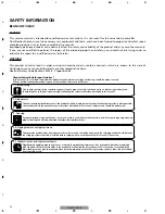
Страница 2: ...and shipping screws To protect the product from damages or failures that may be caused during transit the shipping mode should be set or the shipping screws should be installed before shipping out in accordance with this manual if necessary 1 Product safety You should conform to the regulations governing the product safety radio and noise and other regulations and should keep the safety during ser...

Страница 3: ... kg 6 2 lbs Leads for wiring not included Maximum power output 150 W 2 400 W 1 Continuous power output 75 W 2 at 14 4 V 4 Ω 20 20 000 Hz 0 08 THD 200 W 1 at 14 4 V 4 Ω 20 20 000 Hz 0 8 THD 100 W 2 at 14 4 V 2 Ω 20 20 000 Hz 0 8 THD Load impedance 4 Ω 2 8 Ω allowable Bridge connection 4 8 Ω allowable Frequency response 10 50 000 Hz 0 dB 1 dB Signal to noise ratio 100 dB IHF A network Distortion 0 0...

Страница 4: ...4 1 2 3 4 1 2 3 4 F E D C B A GM X572 XR UC 2 EXPLODED VIEWS AND PARTS LIST 2 1 PACKING ...

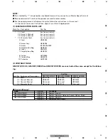
Страница 5: ... the product are used for disassembly For the applying amount of lubricants or glue follow the instructions in this manual In the case of no amount instructions apply as you think it appropriate Owner s Manual Model Part No Language GM X572 XR UC HRD0218 English French GM X572 XR EW HRD0220 English Spanish German French Italian Dutch GM X572 XR ES HRD0222 English Spanish HRD0223 Portuguese B Arabi...

Страница 6: ...6 1 2 3 4 1 2 3 4 F E D C B A GM X572 XR UC 2 2 EXTERIOR ...

Страница 7: ...2 Heat Sink HNR0233 23 Screw PPZ30P100FZK 24 Light Pipe Unit HXA0391 25 Screw ISS30P055FUC 26 Screw PPZ30P100FZK 27 Screw M4x7 HBA0029 28 FET Q612 615 STP55NF06FP 29 Diode D611 FML22R 30 Diode D612 FML22S 31 Fuse FU602 603 20A HEK0020 32 Screw M4x9 HBA0030 33 Screw BBZ30P060FZK 34 Cushion HNM6623 7 5 6 7 8 F E D C B A 5 6 7 8 GM X572 XR UC Mark No Description Part No 1 EXTERIOR SECTION PARTS LIST ...

Страница 8: ...arts of identical designation Symbol indicates a resistor No differentiation is made between chip resistors and discrete resistors NOTE Symbol indicates a capacitor No differentiation is made between chip capacitors and discrete capacitors A AMP UNIT DC DC CONVERTER 15V REGULATOR 15V REGULATOR 1 2 3 4 1 2 3 4 F E D C B A GM X572 XR UC 3 1 OVERALL CONNECTION DIAGRAM Note When ordering service parts...

Страница 9: ...9 A 2R2K 2R2K LEFT SPEAKER OUTPUT HEK0020 HEK0020 FU603 FU602 RIGHT SPEAKER OUTPUT BFC EW ES EW ES UC POWER AMP POWER AMP 5 6 7 8 F E D C B A 5 6 7 8 GM X572 XR UC ...

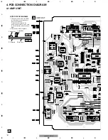
Страница 10: ...E A NOTE FOR PCB DIAGRAMS 1 The parts mounted on this PCB include all necessary parts for several destination For further information for respective destinations be sure to check with the schematic dia gram 2 Viewpoint of PCB diagrams L R L R L R SPEAKER INPUT INPUT GAIN 4 PCB CONNECTION DIAGRAM 4 1 AMP UNIT ...

Страница 11: ...11 5 6 7 8 F E D C B A 5 6 7 8 GM X572 XR UC A SIDE A FRONT BFC FU603 FU602 SPEAKER OUTPUT 1 2 3 1 2 3 1 2 3 1 2 3 1 2 3 1 2 1 2 ...

Страница 12: ...12 1 2 3 4 1 2 3 4 F E D C B A GM X572 XR UC A A AMP UNIT 1 1 1 ...

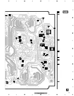
Страница 13: ...13 5 6 7 8 F E D C B A 5 6 7 8 GM X572 XR UC A SIDE B ...

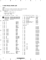
Страница 14: ...ode 1SS133 D 611 Diode FML22R D 612 Diode FML22S D 613 Diode HZS16L 1 D 614 Diode HZS16L 1 D 615 Diode ERA15 02VH D 616 Diode ERA15 02VH D 909 Diode 1SS133 D 911 LED POWER L934BR235SRCF L 501 Choke Coil HTH0011 L 502 Choke Coil HTH0011 L 601 Choke Coil 34µH EW ES model HTH0006 L 602 Choke Coil 75µH EW ES model HTH0010 L 603 Choke Coil 75µH EW ES model HTH0010 L 801 Ferri Inductor CTF1007 L 802 Fer...

Страница 15: ...4J R 918 RD1 4PU472J R 919 RD1 4PU103J R 920 RD1 4PU392J R 921 RD1 4PU103J R 924 RD1 4PU473J R 930 RD1 4PU331J R 931 RD1 4PU331J CAPACITORS C 101 CFTNA224J50 C 102 CFTNA224J50 C 103 CFTNA154J50 C 104 CFTNA154J50 C 201 CEAT100M16 C 202 CEAT100M16 C 301 CCSRCH121J50 C 302 CCSRCH121J50 C 303 CFTNA103J50 C 304 CFTNA103J50 C 501 CEAT220M50 C 502 CEAT220M50 C 503 CEAT101M50 C 504 CEAT101M50 C 505 CEAT22...

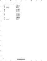
Страница 16: ...C 670 CQMA103J50 C 801 CCSRCH471J50 C 802 CCSRCH471J50 C 803 CEAT100M16 C 804 CEAT100M16 C 805 CQMA472J50 C 806 CQMA472J50 C 807 CCSRCH470J50 C 808 CCSRCH470J50 C 809 CCSRCH470J50 C 810 CCSRCH470J50 C 811 CFTNA105J50 C 812 CFTNA105J50 C 831 CEAT100M16 C 832 CEAT100M16 C 901 220µF 10V HCH0012 Circuit Symbol and No Part Name Part No ...

Страница 17: ...ot shown 3 4 4 4 2 1 Amp Unit 2 Remove the screw and then remove the two Panels 3 Remove the eight screws and then remove the two Heat Sinks 4 Remove the five screws and then remove the Amp Unit Panel 1 1 1 1 1 1 1 Panel Heat Sink Heat Sink 3 3 3 3 3 3 3 4 4 7 GENERAL INFORMATION 7 1 DIAGNOSIS 7 1 1 DISASSEMBLY 6 ADJUSTMENT There is no information to be shown in this chapter ...

Страница 18: ...18 1 2 3 4 1 2 3 4 F E D C B A GM X572 XR UC 7 1 2 CONNECTOR FUNCTION DESCRIPTION ...

Страница 19: ...CTION 2 3 4 10 9 1 8 15 5 6 12 14 13 11 7 1 3 4 7 9 11 13 15 2 5 6 8 10 12 14 STAND BY GND INVERTING INPUT NON INVERTING INPUT SIGNAL GND CLIP AND SHORT CIRCUIT DETECTOR BOOTSTRAP Vs SIGNAL Vs SIGNAL STAND BY MUTE BUFFER DRIVER BOOTSTRAP LOADER Vs POWER OUT Vs POWER 7 2 IC TDA7293V ...

Страница 20: ... control on the front of the power amplifier clockwise If the sound distorts when the volume is turned up turn the gain control counter clockwise When using with an RCA equipped car stereo standard output of 500 mV set to the NORMAL position When using with an RCA equipped Pioneer car stereo with max output of 4 V or more adjust level to match the car stereo output level If you hear too much noise...

Страница 21: ... jack Speaker output terminal See the Connecting the Speaker wires section for speaker connection instructions System remote control wire sold separately Connect the male terminal of this wire to the system remote control terminal of the car stereo SYSTEM REMOTE CONTROL The female terminal can be connected to the auto antenna relay control terminal If the car stereo does not have a system remote c...

Отзывы: