


18
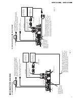
GM-X422, GM-X322
Fuse (30
A)
Grommet
Special red battery wire [RD-222] (sold separately).
After making all other connections at the amplif
ier
,
connect the battery wire terminal of the amplif
ier to
the positi
v
e (+) terminal of the battery
.
Ground wire (black) [RD-222]
(sold separately).
Connect to metal body or chassis.
Fuse (20
A)
Car stereo with
RCA output jacks
External Output
Connecting wires with RCA pin
plugs
(sold separately).
RCA input jack
Speak
er terminal
See the “Connecting the
Speak
er wires”
section
for speak
er connection
instructions.
Blue
Connect the male terminal of this wire to the blue wire of
the car stereo (SYSTEM REMO
TE CONTR
OL).
The
female terminal can be connected to the auto-antenna relay
control terminal. If the car stereo does not ha
v
e a system
remote control terminal,
connect the male terminal to the
po
wer terminal through the ignition switch.
•
Be sure to use the special red battery wire
supplied with the amplif
ier and connect directly to
the battery
. Use the supplied black ground wire
and connect to the v
ehicle body
.
1.
P
ass the battery wir
e fr
om the
engine compartment to the interior
of the v
ehicle.
•
After making all other connections to the
amplif
ier
,
connect the battery wire terminal of
the amplif
ier to the positi
v
e (+) terminal of
the battery
.
2.
Connect the wir
es to the terminal.
•
Fix the wires securely with the terminal
scre
ws.
1.
Expose the end of the speak
er wir
es
by about 10 mm and twist it using
nippers or a cutter
.
2.
Attach lugs to speak
er wir
e ends.
•
Use pliers,
etc.,
to crimp lugs to wires.
3.
Connect the speak
er wir
es to the
speak
er terminals.
•
F
ix the speak
er wires securely with the termi-
nal scre
ws.
UC and ES models:
EW model:
10
mm
Fuse (30A)
Engine
compart-
ment
Interior of
the v
ehicle
Drill an 8-mm
hole into the
v
ehicle body
.
Insert the O-ring rubber
grommet into the v
ehicle
body
.
Positi
v
e terminal
GND terminal
Po
wer terminal
Battery wire
System remote
control terminal
System remote
control wire
(Blue)
Ground wire
T
wist
Speak
er output
terminal
Speak
er wire
T
erminal scre
w
Speak
er wire
Lug
Speak
er output
terminal
Speak
er wire
T
erminal scre
w
Speak
er input
terminal
(3) GM-X322/X1R/UC
-
CONNECTING
THE POWER TERMINAL
-
CONNECTING
THE SPEAKER TERMINALS
Fig. 11
Fig. 12
Fig. 13
Fig. 14
Fig. 15
Fig. 16
Fig. 17
Содержание GM-X322
Страница 4: ...4 GM X422 GM X322 2 2 EXTERIOR Fig 2 ...
Страница 9: ...9 GM X422 GM X322 5 6 7 8 A B C D 5 6 7 8 Fig 4 B A SIDE A OUT IN B ISOLATOR PCB ...
Страница 10: ...10 GM X422 GM X322 A 1 2 3 4 B C D 1 2 3 4 A B B ISOLATOR PCB A MOTHER PCB ...
Страница 11: ...11 GM X422 GM X322 5 6 7 8 A B C D 5 6 7 8 Fig 5 A SIDE B ...


