


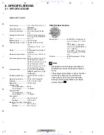
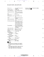


GM-6400F/XJ/UC
9
5
6
7
8
5
6
7
8
C
D
F
A
B
E
2.3 CONNECTION DIAGRAM
1
Special red battery wire
RD-223 (sold separately)
After completing all other amplifier connec-
tions, finally connect the battery wire terminal
of the amplifier to the positive ( ) battery
terminal.
Ground wire (Black)
RD-223 (sold separately)
Connect to metal body or chassis.
Car stereo with RCA output jacks (sold sepa-
rately)
External output
If only one input plug is used, do not connect
anything to RCA input jack B.
Connecting wire with RCA pin plugs (sold se-
parately)
6
RCA output jack
7
RCA input jack A
8
RCA input jack B
9
Amplifier with RCA input jacks (sold sepa-
rately)
a
Speaker output terminals
b
Fuse (25 A) × 2
c
System remote control wire (sold separately)
Connect male terminal of this wire to the sys-
tem remote control terminal of the car stereo
(
SYSTEM REMOTE CONTROL
). The female
terminal can be connected to the auto-anten-
na relay control terminal. If the car stereo
lacks a system remote control terminal, con-
nect the male terminal to the power terminal
via the ignition switch.
d
Fuse (30 A) × 2
e
Grommet
f
Rear side
g
Front side
Note
INPUT SELECT
(input select) switch must be set.
For details, see Setting the Unit.
www. xiaoyu163. com
QQ 376315150
9
9
2
8
9
4
2
9
8
TEL 13942296513
9
9
2
8
9
4
2
9
8
0
5
1
5
1
3
6
7
3
Q
Q
TEL 13942296513 QQ 376315150 892498299
TEL 13942296513 QQ 376315150 892498299


