


8.�
WIRING DIAGRAM
Recommended
W
ire
S
ize
14
Model
(Btu/h)
Power
Supply
ELB
Power
Source
Cable Size
Transmitting
Cable Size
Thermostat
Signal Size
Fuse or Circuit
Breaker (A)
Rated
Current (A)
Nominal
Sensitive
Current
(mA)
24K
~60K
208/230V
~/60Hz
15
30
3×16AWG 5×16AWG
15
5×18AWG/
Max. Running Current (A): REFER TO NAMEPLATE
NOTE:
1. Follow local codes and regulations when selecting field wires, and all the above are the minimum wire size.
2. When transmitting cable is longer than 262ft. (80m), a larger wire size should be selected.
3. Install main switch and ELB for each system separately. Select the high response type ELB that is acted within
0.1
second.
4. If auxiliary heater is required and already installed on indoor unit, power source cable should be installed separately
and the size should be selected in accordance with UL.
6×18AWG
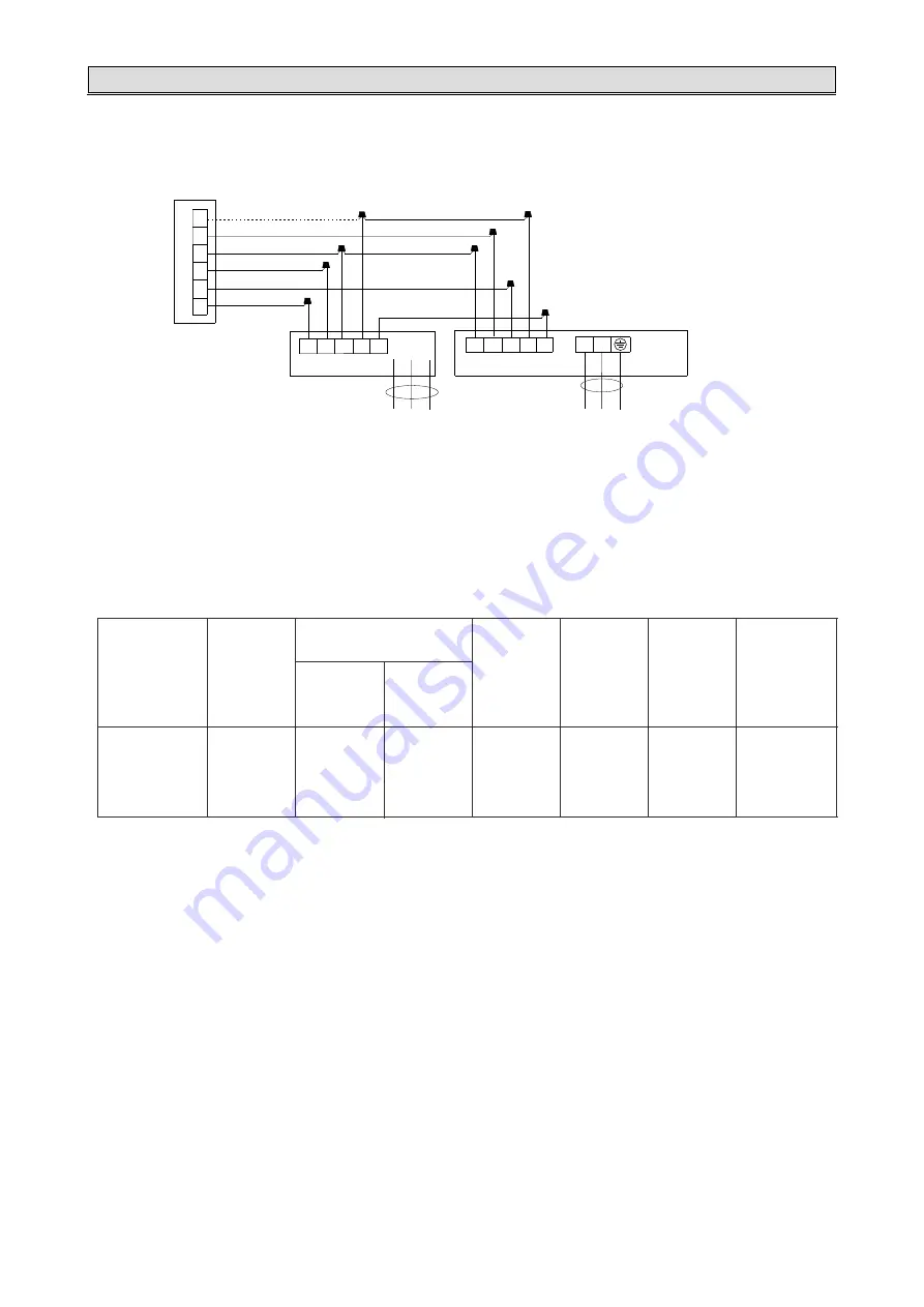
8.3 Common
W
iring
Wiring
D
iagram
L1 L2 PE
Power
S
upply
Power
S
upply
Thermostat
Indoor
U
nit
Outdoor
U
nit
Power
T
erminal
P
anel
(L1)(L2)( )
W1
B
C
R
Y
G
C B Y W SI
G R C W1 SI
NOTE:
(1) Do
not
connect
dashed
line
when
electric
heater
is
not
used
.
(2) Wiring
must
be
performed
according
to
wiring
diagram
that
pasted
on
indoor
unit
.
(3) The SI wire between the indoor and outdoor units is not indispensable, especially when the outdoor unit is connected to
an indoor unit of a different brand. It is more energy-saving when the outdoor unit is connected to an indoor unit of the
same brand by SI wire. However, it still can run without it.
(4) Since the thermostat is locally provided, the terminal block in the diagram may differ from the actual one. The letter Y is
the same as Y1.


