background image

IN

DEX

8

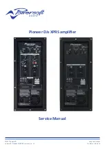
Pioneer DJs XPRS

 | SERVICE MANUAL

7. Testing and Troubleshooting

Is Pioneer Full-Range

LM12FR-ES (PF00V336) _LM15FR-ES (PF00V346) _LM10FR-ES (PF00V348)

Is Pioneer Subwoofer

LM15SW-ES (PF00V337)_LM115SW-ES (PF00V347)

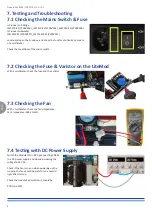
Locate and open the Fuse Box, and check the fuse for continuity by means 

of a multimeter.

Check the conditions of the mains switch.

With a multimeter, check the fuse and the varistor

With a multimeter, check the fan’s impedance 

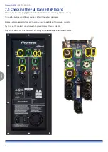
Fan’s Impedance: 385 KΩ ±5%

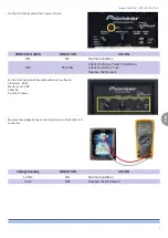
Switch the Module ON in DC by connecting CN101 

to a DC power supply, and slowly increasing the 

voltage to 60 Vdc.

Check if the Fan turns on when powering up the 

module, the fan should operate for one second 

right after start up.

Check the module’s absorption, it should be:

250 mA ± 10%

7.1 Checking the Mains Switch & Fuse

7.2 Checking the Fuse & Varistor on the LiteMod

7.3 Checking the Fan

7.4 Testing with DC Power Supply

Содержание DJ XPRS

Страница 1: ...Pioneer DJs XPRS amplifier Service Manual Keep this manual for future reference 2017 Powersoft powersoft_Pioneer DJs XPRS_servman_en_v2 ...

Страница 2: ...Intentionally left blank ...

Страница 3: ...1 DSP Board Full Range 9 2 2 DSP Board Subwoofer 10 Running Test with PT Lite 10 1 Testing the Full Range 10 2 Testing the Subwoofer 11 Replacement Parts for IS Pioneer Full Range 12 Replacement Parts for IS Pioneer Subwoofer Pioneer DJs XPXS Service Analysis and Solution A Analysis and Solution 1 Amp Module Verify as in Chap 7 2 Chap 7 4 Chap 8 refer to Chap 9 1 to remove replace if required 2 DS...

Страница 4: ...ten permission from Powersoft S p A Should the service centre agreement between the two companies be interrupted these documents must be returned to Powersoft S p A Italy or proof of their destruction be provided CAUTION RISK OF ELECTRIC SHOCK DO NOT OPEN Required Instrumentation Q ty Example Comments Dual stabilized power supply 30 Vdc 5 A 2 APLHA Electronica mod AL852D or equivalent Digital Osci...

Страница 5: ...INDEX 5 Pioneer DJs XPRS SERVICE MANUAL 4 Requirements for Testing with PT Lite Tester CB000521 CB000737 00 CB000677 Noise Termination Connectors PC PT Lite Testing Unit ...

Страница 6: ... Is Pioneer Full Range LM12FR ES PF00V336 _LM15FR ES PF00V346 _LM10FR ES PF00V348 Pioneer Model Pioneer Product Serial Number Pioneer Model Pioneer Product Serial Number Powersoft Product Code Powersoft Product Serial Number Is Pioneer Subwoofer LM15SW ES PF00V337 _LM115SW ES PF00V347 ...

Страница 7: ...woofer LM15SW ES PF00V337 _LM115SW ES PF00V347 6 Internal Layout LiteMod Components Is Pioneer Full Range LM12FR ES PF00V336 _LM15FR ES PF00V346 _LM10FR ES PF00V348 Is Pioneer Subwoofer LM15SW ES PF00V337 _LM115SW ES PF00V347 Litemod Serial Number Power Amp CH2 Power Supply Stage Fuse ON OFF Switch Power Amp CH1 Fan Varistor DSP Board Part Number Outputs ...

Страница 8: ...witch With a multimeter check the fuse and the varistor With a multimeter check the fan s impedance Fan s Impedance 385 KΩ 5 Switch the Module ON in DC by connecting CN101 to a DC power supply and slowly increasing the voltage to 60 Vdc Check if the Fan turns on when powering up the module the fan should operate for one second right after start up Check the module s absorption it should be 250 mA ...

Страница 9: ... Check the Mains Switch Condition Check the Mains Fuse Replace the Module Set the front panel switches and positions as portrayed Cross Over 80 Hz Master Level 0 dB Phase 0o Front LED Power Measure the voltage between the K and A pins on the PL612 LED connector Voltage Reading CONDITION ACTION 12 Vdc OK Normal Condition 0 Vdc FAIL Replace the DSP Board ...

Страница 10: ...witches to different positions feel if there s any damaged Rotate the Potentiometers from end to end up and down feel if it is moving smoothly Try to clean the contact connector with Approved Contact Cleaner let dry Any of the Switches or Potentiometers are damaged replace the DSP Board when necessary 7 5 Checking the Full Range DSP Board ...

Страница 11: ...witches to different positions feel if there s any damaged Rotate the Potentiometers from end to end up and down feel if it is moving smoothly Try to clean the contact connector with Approved Contact Cleaner let dry Any of the Switches or Potentiometers are damaged replace the DSP Board when necessary 7 6 Checking the Subwoofer DSP Board ...

Страница 12: ... located as portrayed CH1 CH2 Diagnostic LEDs Refer to the following table and follow the instructions portrayed within CH2_LD1 green CH2_LD2 red CH1_LD3 red CH1_LD4 green Channel s Condition ACTION ON OFF OFF ON OK Normal Operating Condition apply Input Signal ON ON ON ON Module is Damaged Replace the Module OFF ON ON OFF CH1 CH2 are Damaged Replace the Module OFF OFF OFF OFF Module is Damaged Re...

Страница 13: ...Unscrew the 10 Torx T10 Screws highlighted in Yellow 9 1 Disassembling the LiteMod Unplug the 3 Cables connected to the Module highlighted in Green Unplug the Flat Cable by gently pulling on the connector s sides highlighted in Blue Unscrew the 4 Philips Head Screws highlighted in Yellow ...

Страница 14: ...lug the 3 Cables connected to the Module highlighted in Green Unplug the Flat Cable by gently pulling on the connector s sides highlighted in Blue Remove the 8 nuts washers by an M7 Socketed Screwdriver highlighted in Yellow Unplug the Cable highlighted in Green Now the DSP Board is able to access 9 2 Disassembling the DSP Board ...

Страница 15: ...Faulty DSP Board is able to remove replace with a New DSP Board Pull out the 2 Switch Knobs 3 Potentiometer Knobs hightlighted in Blue Unscrew the 5 Torx T8 Screws highlighted in Yellow Unscrew the 11 Philips Head Screws highlighted in Green 9 2 1 DSP Board Full Range ...

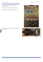
Страница 16: ...remove replace with a New DSP Board Pull out the Switch Knob Potentiometer Knob hightlighted in Blue Unscrew the 5 Torx T8 Screws highlighted in Yellow Unscrew the 8 Philips Head Screws highlighted in Green 9 2 2 DSP Board Subwoofer Pioneer DJs XPRS SERVICE MANUAL ...

Страница 17: ...n Input the Product Code Serial Number 10 1 Testing the Full Range Check if the Test Plan has been successfully loaded The Status Cell will show LOADED Check the Product Code and Serial Number Launch the test by clicking on START 2 1 Provide 230Vac Power On follow the connections Verified if the Fan is running when Power On 3 Measure the voltage between the K and A pins on the PL612 LED connector ...

Страница 18: ...TE The attenuators are not present in the new PTE version AT000078 01 This process is automatic The Noise Terminations must be connected to the amp s channel inputs 1 2 when this message is prompted The terminations are not needed for the new PTE version AT000078 01 Follow the instruction that will be prompted on your screen NOTE The attenuators are not present in the new PTE version AT000078 01 T...

Страница 19: ...INDEX 19 Pioneer DJs XPRS SERVICE MANUAL 9 10 11 12 13 ...

Страница 20: ...INDEX 20 18 Pioneer DJs XPRS SERVICE MANUAL 14 15 16 17 Connect the Amplifier s MIC LINE 2 Input to the Line Output CH A on the PT Lite Line 1 is NOT to be CONNECTED ...

Страница 21: ...INDEX 21 Pioneer DJs XPRS SERVICE MANUAL 19 20 Now the PT Lite had completed and passed the test The software will prompt you with a message asking if a printed version of the certificate is required ...

Страница 22: ...INDEX 22 X4 SERVICE MANUAL ...

Страница 23: ...DEX 23 X4 SERVICE MANUAL Pioneer DJs XPRS SERVICE MANUAL 5 6 7 8 9 10 3 4 2 1 After Completion of the PT Lite Test you may refer to the report to view the test results C Powersoft P Collaudo Report PTLite ...

Страница 24: ...INDEX 24 Pioneer DJs XPRS SERVICE MANUAL 11 12 13 14 15 16 17 18 ...

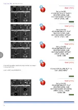
Страница 25: ...RS SERVICE MANUAL Launch PTELite Sofeware to begin the PT Lite Test for PF00V337 PF00V347 PIONEER SUBWOOFER Click on Manual Load then Input the Product Code Serial Number Click START to begin testing 10 2 Testing the Subwoofer 5 6 2 3 4 1 7 8 ...

Страница 26: ...INDEX 26 Pioneer DJs XPRS SERVICE MANUAL 9 10 11 12 13 14 15 16 The PT Lite software will prompt you with a message asking if a printed version of the certificate is required ...

Страница 27: ...INDEX 27 Pioneer DJs XPRS SERVICE MANUAL 5 6 2 3 4 1 7 8 9 10 After Completion of the PT Lite Test you may refer to the report to view the test results C Powersoft P Collaudo Report PTLite ...

Страница 28: ...UT SUB INTERFACE Customized x PF00V336 SMC01041 346 R DSP34P2IN2OUT SUB INTERFACE Customized x PF00V346 SMC01041 348 R DSP34P2IN2OUT SUB INTERFACE Customized x PF00V348 SM001052 R DSP34P2IN2OUT BASIC SWITCH SMC01053 R DSP34P2IN2OUT BASIC SPEAKER CABLE GASKET CN000373 AC INLET 10A 250 Vac W SWITCH AND FUSE HOLDER ME001058 01 LITEMOD_IS PIONEER FRONTAL PLATE FW VERSION ...

Страница 29: ...TIOMETER FU000025 Fuse 4A 250Vac 5x20mm Time Lag 215_Series VN000034 FAN ASSEMBLY CABLE LENGHT 200 mm mod _ADDA_AD0612DS D70GL W60D60H15 VI000163 BLACK M4X12 mm HEX SCREW VI000117 BLACK M3X10 mm HEX SCREW VI000136 BLACK 2 9x9 5x5 2 mm PHILLIPS HEAD SCREW ET000571 00 LITEMOD_PIONEER LABEL FOR PANEL LM12FR ES SIZE39X7 ET000573 00 LITEMOD_PIONEER LABEL FOR PANEL LM15FR ES SIZE39X7 ...

Страница 30: ...TEMOD SMC01042 337 R DSP34P2IN2OUT SUB INTERFACE Customized x PF00V337 SMC01042 347 R DSP34P2IN2OUT SUB INTERFACE Customized x PF00V347 SM001052 R DSP34P2IN2OUT BASIC SWITCH SMC01053 R DSP34P2IN2OUT BASIC SPEAKER CABLE GASKET CN000373 AC INLET 10A 250 Vac W SWITCH AND FUSE HOLDER ME001057 01 LITEMOD_IS PIONEER FRONTAL PLATE SW VERSION ...

Страница 31: ...ITEMOD_IS PIONEER KNOB FOR POTENTIOMETER FU000025 Fuse 4A 250Vac 5x20mm Time Lag 215_Series VN000034 FAN ASSEMBLY CABLE LENGHT 200 mm mod _ADDA_AD0612DS D70GL W60D60H15 VI000163 BLACK M4X12 mm HEX SCREW VI000117 BLACK M3X10 mm HEX SCREW VI000136 BLACK 2 9x9 5x5 2 mm PHILLIPS HEAD SCREW ET000572 00 LITEMOD_PIONEER LABEL FOR PANEL LM15SW ES SIZE39X7 ...

Страница 32: ...orn Observe precaution for handling Electrostatic Discharge sensitive devices Safety precautions We recommend to follow all precautions stated by the law while handling sensitive electrical components AlloftheservicingworkmustbecarriedinaEPAESDcompliantenvironment with the exception of the mere handling of the mechanical parts An ESD protected workstation consists in Static Dissipativeworkingsurfa...

Страница 33: ...Intentionally left blank ...

Страница 34: ...ble on www powersoft audio com Powersoft S p A Via Enrico Conti 5 50018 Scandicci FI Italy Tel 39 055 735 0230 Fax 39 055 735 6235 General inquiries info powersoft it Sales sales powersoft it Application technical support support powersoft it Service maintenance service powersoft it powersoft audio com ...

Отзывы: