background image

1

Contents

Dear Customer ............................................ 3

Key Finder .................................................... 4

Head Unit (DEX-P9)  ........................................ 4
Remote Controller (DEX-P9) ............................ 4
Opening and Closing 

the Remote Controller Cover  .................... 5

-

When the Cover is Closed

-

When the Cover is Open

Before Using This Product  ...................... 7

About This Product  .......................................... 7
About This Manual ............................................ 7
Important .......................................................... 8
About the Digital Network  ................................ 8
MODE Switch Setting  ...................................... 9
Resetting the Microprocessor  ..........................10
Precaution ........................................................ 11
After-sales Service for Pioneer Products  ........ 12

Audio Adjustment  .................................... 13

Audio Menu  .................................................... 13

-

Switching to the Audio Menu

Audio Adjustment <Main>  .................... 15

Main Menu  ...................................................... 15

-

Switching to the Main Menu

Fader/Balance Adjustment  .............................. 15
Bass/Treble Adjustment  .................................. 16
Adjusting the Listening Position  .................... 17

-

Using the Position Selector

-

Fine Tuning the Position

-

Effective distance Adjustment 
Using the Position Fine Tuning function

Source Level Adjustment  ................................ 21

Audio Adjustment <Equalizer> .............. 22

Equalizer menu ................................................ 22

-

Switching to the Equalizer Menu

Relation Between Frequency Characteristics 

and Sound Quality .................................... 23

Adjusting the 31 Band Graphic Equalizer  ...... 25
The Flat function  ............................................ 26

Содержание DEQ-P9

Страница 1: ...Universal Digital Preamp Equalizer Owner s Manual DEQ P9 ENGLISH ESPAÑOL DEUTSCH FRANÇAIS ITALIANO NEDERLANDS ...

Страница 2: ...eer Products 12 Audio Adjustment 13 Audio Menu 13 Switching to the Audio Menu Audio Adjustment Main 15 Main Menu 15 Switching to the Main Menu Fader Balance Adjustment 15 Bass Treble Adjustment 16 Adjusting the Listening Position 17 Using the Position Selector Fine Tuning the Position Effective distance Adjustment Using the Position Fine Tuning function Source Level Adjustment 21 Audio Adjustment ...

Страница 3: ...ent Data in Memory 40 Recalling Data Stored in Memory 41 Recalling Memory Using Forward Reverse Order Functions of Equalizer Menu Specifying the Memory Number Directly Memory Protect function 43 Memory Clearing Operations 44 Display for the Person who Set Up the Audio Adjustments 45 Inputting the Name 45 Inputting Characters 45 Memory Data Memo 48 Connecting the Units 51 Routing the Optical Cable ...

Страница 4: ...t the dial and leave it there Taking a minute to do this now will help to prevent hearing damage or loss in the future After all we want you listening for a lifetime We Want You Listening For A Lifetime Used wisely your new sound equipment will provide a lifetime of fun and enjoyment Since hearing damage from loud noise is often undetectable until it is too late this manufacturer and the Electroni...

Страница 5: ...les the SHIFT RETURN and FUNCTION buttons 1 6 inside this unit For more details refer to the page 5 Closed state Open state 5 2 3 buttons BAND button MENU button FUNCTION buttons 1 6 RETURN button SHIFT button BAND button 5 2 3 buttons These buttons can not be used in the Audio Adjustment operation 4 ENGLISH ESPAÑOL DEUTSCH FRANÇAIS ITALIANO NEDERLANDS ...

Страница 6: ... enables the SHIFT RETURN and FUNCTION buttons 1 6 inside the unit Menu displays with cover open and closed in this system the available functions and the menu display vary depending on the condition of the remote controller in use Remote Controller Menu display Cover closed Closed state Cover open Open State ...

Страница 7: ...troller makes the menu display to the open state Menu display in open state Example Main Menu Setting Screen Note Positions of menu items on the display correspond to the positions of FUNCTION buttons 1 6 Menu display in open state Using FUNCTION buttons 1 6 operable functions are displayed When the cover is closed in the middle of operation Closing the cover during operation releases the previous...

Страница 8: ... you benefit fully from their potential and to maximize your listening enjoyment We recommend that you familiarize yourself with the functions and their operation by reading through the manual before you begin using this product It is especially important that you read and observe the Precaution on page 11 and in other sections This manual mainly explains the remote controller operation In some fu...

Страница 9: ...ounds because of the confined space and complex shape within a vehicle This disturbs frequency characteristics and significantly reduces sound quality The orientation of the sound image becomes unnatural because speakers may not be installed symmetrically to left and right of the listener or because speakers are installed in both the front and rear This system is equipped with a wide variety of fu...

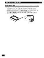
Страница 10: ...the equalizer and network adjustment independently between Left and Right channel LR COM mode can be adjusted these adjustment simultaneously between Left and Right channel Since usable functions are dif ferent between LR IND and LR COM be sure to set the mode correctly Set MODE switch of this product to appropriate position with a pen tip or other pointed instrument ...

Страница 11: ...fter installation When the machine fails to operate properly When strange incorrect messages appear on the display When setting the position of the MODE switch of this product To reset the microprocessor press the RESET button on this unit with a pen tip or other pointed instrument 10 ENGLISH ESPAÑOL DEUTSCH FRANÇAIS ITALIANO NEDERLANDS ...

Страница 12: ...nds to be audible Protect the product from moisture If the battery is disconnected the preset memory will be erased and must be repro grammed CAUTION USE OF CONTROL OR ADJUSTMENT OR PERFOR MANCE OF PROCEDURES OTHER THAN THOSE SPEC IFIED HEREIN MAY RESULT IN HAZARDOUS RADIA TION EXPOSURE CAUTION THE USE OF OPTICAL INSTRUMENTS WITH THIS PRODUCT WILL INCREASE EYE HAZARD ...

Страница 13: ...t ship your product to the companies at the addresses listed below for repair without advance contact For warranty information please see the Limited Warranty sheet included with your product 12 ENGLISH ESPAÑOL DEUTSCH FRANÇAIS ITALIANO NEDERLANDS 7 U S A Pioneer Electronics Service Inc CUSTOMER SERVICE DEPARTMENT P O Box 1760 Long Beach CA 90801 800 421 1404 7CANADA Pioneer Electronics of Canada ...

Страница 14: ...quency disturbance in a vehicle The Equalizer function for the component can make fine adjustments of sound quality for each frequency Network Network page 27 This adjusts the reproduced frequency band cross over frequency and the level of each sound range band when a multi amp system is set up It also corrects unnatural orienta tion of the sound image caused by the locations of the speakers using...

Страница 15: ...Menu Network Network Menu 3 Press the BAND button and cancel the Audio Menu Cancel the Audio Menu to return to the operations screen of the source currently in use 2 Operate the mode 1 Each press of MENU button selects the desired Audio Menu in the following order 14 ENGLISH ESPAÑOL DEUTSCH FRANÇAIS ITALIANO NEDERLANDS ...

Страница 16: ...the remote controller refer to page 5 switches between the open and closed states of the menu display and setting screen To cancel the Main Menu press the BAND button Fader Balance Adjustment FAD BAL CONTROL Closed state This function allows you to select a fader balance setting that provides ideal listening conditions in all occupied seats This function can be operated with the remote controller ...

Страница 17: ... Perform Bass Treble Adjustment to adjust overall sound quality 5 Press the 5 buttons and adjust the level Holding down these buttons continues their operations with one stop at the central position 4 Press the 2 3 buttons and select a frequency point Tune to the desired frequency point 3 Press the FUNCTION button 1 again to choose bass BASS or treble TREB Pressing the button switches bass treble ...

Страница 18: ...ont Seat Right Using the Position Selector POSI Experimenting with other positions The position is normally designed to match the listener s position in the car However other positions may prove to be more effective depending on the model of the car and the location of the speakers Compare the sound and choose the position in which the sounds are most natural 4 Press one of buttons 2 3 5 and selec...

Страница 19: ...ound image thus moves in the direction in which the value for the difference in sound levels is closer to 0 Relationship between the distance and the delay time It is necessary to adjust the delay time irrespective of the distance between the listening position and each speaker unit for better sound quality With this system when you adjust the distance the corresponding delay time is conducted aut...

Страница 20: ...g has been completed press the RETURN button to cancel the Position Fine Tuning Screen The values are stored in memory and the display returns to Position Selector Screen 4 Press the 2 3 buttons to correct the position of the sound image Holding down these buttons continues their operations during distance tuning holding down the button moves the distance 1 34 in 1 step ...

Страница 21: ...store the displayed values in memory as new values for the Time Alignment Adjustment function standard values for the Position Fine Tuning function adjust any one value again using the 5 buttons The displayed values will be stored in memory and the distance between the lis tening position and each speaker set using the Position Fine Tuning function will be reset and returned to 0 When the distance...

Страница 22: ...other than tuner The head unit s CD player Multi CD player and DVD player are set to the same volume adjust ment setting automatically AUX External 1 and External 2 are set to the same volume adjustment setting automatically 5 Increase or decrease the level with the 5 buttons The display shows 4 4 4 Press Function button 3 on MAIN Menu Setting Screen The display switches to SLA Adjustment Screen 2...

Страница 23: ...r Curves Open state Refer to page 39 Switching to the Equalizer Menu After the title screen the display switches to the operation screen of the Equalizer Menu Opening and closing the cover of the remote controller refer to page 5 switches between the open and closed states of the menu display and setting screen To cancel the Equalizer Menu press the BAND button Press the MENU button and select the...

Страница 24: ...ere the sound outline is created A lack of sound in this range results in a lack of warmth Excessive sound dims clarity t The sound range required for the core of the sound A lack of sound in this range weakens the core An important range for keeping the overall sound quality in balance y In this range the sharp expansive sounds of the brass and electric guitar are felt However excessive sound in ...

Страница 25: ...subwoofer is connected Adjust the treble to a lower volume to match the weaker bass and create a well balanced sound Noises coming from the road make the bass seem weak while driving If the level is below 100 Hz adjust to a slightly greater level to maintain superb sound balance while driving When the sound is inadequate or excessive it is recommended to set the levels after checking the frequenci...

Страница 26: ...after the adjustments are completed Refer to page 38 for Memory operations 6 Switch between right and left to set up the equalizer curve Repeat steps 2 5 to set up equalizer curves for the left and right speakers separately 5 Adjust the other bands Repeat steps 3 and 4 to adjust to the desired sound 4 Press the 5 buttons and adjust the level 3 Press the 2 3 buttons and select the desired band freq...

Страница 27: ...usted equalizer curve Note When the Flat function is ON the Equalizer Adjustment or Memory operations of the Equalizer curve can not be conducted 2 Press the FUNCTION button 1 switches the Flat function ON OFF FLT is displayed when the Flat function is ON 1 Open the cover of the remote controller in the Equalizer Menu refer to page 5 This switches to Equalizer Menu Setting Screen 26 ENGLISH ESPAÑO...

Страница 28: ...ch frequency range by an exclusive power amplifier It is possible to reduce the modulation distortion rate since high range signals are not effected by strong signals in the low range As it is possible to select amplifiers and speakers to suit the characteristics of each fre quency range the load on each unit is reduced ensuring optimum performance Under the multi amp system it is necessary to div...

Страница 29: ...lt Adjusting the Network requires technical skills and knowledge of the amplifiers and speakers installed in the system Consult your dealer from which the products were purchased if adjustments are difficult When adjustments have already been made at your dealer the optimum setup for vehicle s particular interior has already been installed in the memory In this case recall the corresponding memory...

Страница 30: ...aker units In order to adjust the Time Alignment Adjustment function more easily this System allows the delay time to be set up by simply inputting the difference in the distance between speaker units the distance to be corrected The delay time will be automatically calculated by this system Although the distance from each speaker unit varies depending on the position of the listener the first set...

Страница 31: ...rements are made as this information may prove useful at a later date Measure the distances to be corrected in the same manner for other systems than those used in the above example Left Speaker L Front tweeter high range Front mid bass mid low range Front bass low range Front tweeter high range Front mid bass mid low range Front bass low range Right Speaker R Subwoofer ultrabass range Subwoofer u...

Страница 32: ... following order 4 Press FUNCTION buttons 3 or 4 and select the speaker channel to input Press the buttons to switch between left LEFT and right RIGHT 3 Press the FUNCTION button 5 and select the driver s seat posi tion Press the buttons to switch between FRONT R and FRONT L Select the position when measuring the distance to be corrected as shown on the page 30 2 Press the FUNCTION button 2 The di...

Страница 33: ...ts for the other speaker units Repeat steps 4 6 to input the distance to be corrected for each speaker unit 6 Press the 5 buttons to input the distance to be corrected delay time Input the distance to be corrected as measured on page 30 Holding down these buttons continues their operations during distance tuning holding down the button moves the distance 1 34 in 1 step 32 ENGLISH ESPAÑOL DEUTSCH F...

Страница 34: ...Hz 250 Hz 10 kHz 24 0 dB Mid range 200 Hz 10 kHz 2 kHz 20 kHz 24 0 dB High range 1 6 kHz 20 kHz 8 kHz 20 kHz 24 0 dB Slope adjustment PASS 6 dB oct 36 dB oct Every 6 dB oct total of 6 steps The slope inclination of attenuation of filter characteristics of H P F and L P F is set up Note When the slope is set as PASS the audio signals bypass the filter circuit cutting out the effect of the filter ci...

Страница 35: ...s When the position is set up for the driver s seat after adjusting the distance between the listening position and each speaker of the Time Alignment Adjustment function refer to page 29 it is rec ommended that filter adjustments be made Store the different filter characteristics into memory by the listening position set up with the Position Selector function refer to page 17 or by the source bei...

Страница 36: ...s the basic frequencies of many musical instruments It is recommended that the level adjustment of the low band be made first and then the level adjustment of the mid high and subwoofer be made in that order 6 Set up the cut off frequencies of each filter for all the bands Repeat steps 4 and 5 to adjust each filter so that the band used and crossover frequency are appropriately located 5 Press the...

Страница 37: ...R and reverse REV Set up the one which makes the better link to the next band 8 Press FUNCTION button 3 and adjust the slope of each filter Press the button to change the adjustment values The slope can be set up for either the high pass filter or the low pass filter When setting up have in mind the adjustments to be made to the next band 7 Press the 5 buttons and adjust the level of each band Hol...

Страница 38: ...ar and high quality bass rage In this case adjust the cut off frequency to 20 40 Hz and adjust the slope to 18 36 dB oct If the subwoofer is installed in the rear tray setting up the slope of the low pass filter gently 6 12 dB oct gives the listener the feeling that the sound dwindles to the rear with a resultant dis tortion of the forward sound image position It is recommended to set the slope at...

Страница 39: ...n memory Memory 5 This memory stores the equalizer curve and network setup that have been adjusted to the desired position The memory operations storing recalling etc are carried out using each menu screen In this manual the memory operations that are common to all the menus are illustrated mainly using the screens for a 31 band graphic equalizer Conduct the same operations on other menus Note Pre...

Страница 40: ...n or Time Alignment Adjustment Screen 2 Press the SHIFT button The display switches to Network Memory Operation Screen for conducting memory operations Press the button again to return to the previous screen 1 Open the cover of the remote controller in the Network Menu refer to page 5 2 Press the SHIFT button The display switches to Equalizer Memory Operation Screen for conducting memory operation...

Страница 41: ...5 or cancel the protect func tion To cancel the protect function the memory to be canceled must be recalled Therefore the current adjustment data is cleared When the Protect function has been canceled make the adjustment again 4 Press the SHIFT button to cancel memory mode The display returns to the previous screen 3 To store in memory press the FUNCTION button corresponding to the desired memory ...

Страница 42: ... FUNCTION buttons Note It is not possible to recall the memory in this manner when operating the network menu Specifying the Memory Number Directly This function can be operated when the cover of the remote controller is open and the menu displays open state Stored data can be retrieved directly Recalling Memory Using Forward Reverse Order Functions of Equalizer Menu 2 Press the 5 buttons to recal...

Страница 43: ...memory clears the adjustment data Store the adjustment data into memory when necessary refer to page 40 2 Press the FUNCTION button to recall the memory Press the FUNCTION button which corresponds to the desired memory number 1 Switch to the memory mode of each menu refer to page 39 The display switches to Memory Operations Screen of each menu 42 ENGLISH ESPAÑOL DEUTSCH FRANÇAIS ITALIANO NEDERLAND...

Страница 44: ...is protected simultaneously You cannot operate the Protect function on M5 memory When turning the Protect function ON OFF Turning the Protect function ON OFF does not bring up anything on the display When the Protect function is turned ON and the user attempts to store new data in that memory the appears to signify that data storage is not possible 2 Press the RETURN button for two seconds to turn...

Страница 45: ...s Note When the Protect function is turned ON it is not possible to clear the memory 2 Press the FUNCTION button 6 for two seconds to clear the memory 1 Recall the memory to be cleared by clearing operation refer to page 42 Specify the memory number directly to recall the memory 44 ENGLISH ESPAÑOL DEUTSCH FRANÇAIS ITALIANO NEDERLANDS ...

Страница 46: ... contents are displayed Note A maximum of 20 characters can be stored The same contents are displayed on the title screen of all the Audio menus Inputting Characters Switching to the Edit Mode Characters are input in Edit Mode EDIT 3 Press the SHIFT button for two seconds to switch to Edit Mode The display switches to Character Input Screen to allow input of characters 2 Open the cover of the remo...

Страница 47: ...ip the box with the 3 button 5 Select letters numbers and sym bols with the 5 buttons 4 Switch the desired character type with FUNCTION button 1 Each press of FUNCTION button 1 changes the Character type in the fol lowing order Upper case alphabet Capital Letter Numbers and Symbols Lower case alphabet Small Letter 46 ENGLISH ESPAÑOL DEUTSCH FRANÇAIS ITALIANO NEDERLANDS ...

Страница 48: ... the audio in memory Removing the car battery clears the memory 9 The contents stored in memory are indicated on the display Switching the Audio Menu displays on the title screen the contents stored in memory 8 Press the FUNCTION button 6 or RETURN button and return to the previous mode 7 When you have completed title input memorize by pressing the FUNCTION button 5 ...

Страница 49: ... NEDERLANDS Frequency 20 Hz 25 Hz 31 5 Hz 40 Hz 50 Hz 63 Hz 80 Hz 100 Hz 125 Hz 160 Hz 200 Hz 250 Hz 315 Hz 400 Hz 500 Hz 630 Hz 800 Hz 1 kHz 1 25 kHz 1 6 kHz 2 kHz 3 15 kHz 4 kHz 5 kHz 6 3 kHz 8 kHz 10 kHz 12 5 kHz 16 kHz 20 kHz M1 M2 M3 M4 M5 Equalizer 2 5 kHz ...

Страница 50: ... P F LEFT RIGHT M5 L P F H P F LEFT RIGHT Level Frequency Slope Frequency Phase Slope Level Frequency Slope Frequency Phase Slope Level Frequency Slope Frequency Phase Slope Level Frequency Slope Frequency Phase Slope Level Frequency Slope S W LOW MID HIGH S W LOW MID HIGH S W LOW MID HIGH S W LOW MID HIGH S W LOW MID HIGH S W LOW MID HIGH ...

Страница 51: ...S W LOW MID HIGH M4 S W LOW MID HIGH M5 S W LOW MID HIGH Left LEFT Right RIGHT Position Left LEFT Right RIGHT Position Left LEFT Right RIGHT Position Left LEFT Right RIGHT Position Left LEFT Right RIGHT Position 50 ENGLISH ESPAÑOL DEUTSCH FRANÇAIS ITALIANO NEDERLANDS ...

Страница 52: ...o work when it should Never feed power to other equipment by cutting the insulation of the power supply lead of the unit and tapping into the lead The current capacity of the lead will be exceeded causing overheating When replacing a fuse be sure to use only fuses of the rating prescribed on the fuse holder The black lead is ground Please ground this lead separately from the ground of high current...

Страница 53: ...s on it and so that it cannot be stepped on or caught in anything for instance a door Make a loop of diameter at least 200 mm 7 7 8 inches with the remaining optical cable so that the cable does not get strained When plugging the optical cable into the unit use the supplied cable cramp to prevent the cables from being bent sharply Route the optical cable so that it does not get caught in moving pa...

Страница 54: ...em Fuse 4A Fuse holder Power Terminal Refer to Connecting the Power Terminal on page 51 Yellow To terminal always supplied with power regardless of ignition switch position Black ground To vehicle metal body Blue white To system control terminal of the power amp max 300 mA 12 V DC RCA OUTPUT See Connecting the RCAInput Amprifier Connecting the Units ...

Страница 55: ...lifier Tweeter Mid range Woofer Subwoofer White White Red Red Power Amplifier Power Amplifier Power Amplifier Power Amplifier For system remote control Blue white Blue white 54 ENGLISH ESPAÑOL DEUTSCH FRANÇAIS ITALIANO NEDERLANDS ...

Страница 56: ...ort circuit 2 Connecting the leads Securely fasten the leads with terminal screws 3 Cover the entire terminal with the short circuit protection cover REMOTE BACK UP GND REMOTE BACK UP GND Short circuit protection cover REMOTE BACK UP GND Terminal screw Black lead ground Ground terminal REMOTE BACK UP GND Terminal screw Yellow lead Blue white lead Short circuit protection cover ...

Страница 57: ...able Connecting the Cables 2 Route the optical cable and IP BUS cable through the cable clamp Attach the cable clamp into the hole 1 Attach the cable clamp When plugging the optical cable and IP BUS cable into the unit use the supplied cable cramp to prevent the cables from being bent sharply ...

Страница 58: ... can cause malfunction Consult with your nearest dealer if installation requires the drilling of holes or other modifications of the vehicle Install the unit where it does not get in the driver s way and cannot injure the passenger if there is a sudden stop like an emergency stop Installing the Unit 1 Install the brackets to the bottom of the unit 2 Install the unit to the vehicle Tapping screw 4 ...

Страница 59: ... battery connected An yellow lead is not Connect all yellow leads 53 properly connected to the battery terminal 55 supplied with constant power regardless of the ignition switch position after running them through the vehicle s fuse unit A black lead ground is Firmly connect all the black 53 not properly connected leads to the vehicle metal 55 body A blue white lead is not Connect the blue white 5...

Страница 60: ...24 dB 0 5 dB MID HPF frequency 200 Hz 10 kHz 1 3 oct LPF frequency 2 kHz 20 kHz 1 3 oct Gain 0 dB 24 dB 0 5 dB HIGH HPF frequency 1 6 kHz 20 kHz 1 3 oct LPF frequency 8 kHz 20 kHz 1 3 oct Gain 0 dB 24 dB 0 5 dB Slope PASS 6 12 18 24 30 36 dB oct PASS no pass HPF High channel Phase NORMAL REVERSE Time alignment 0 134 in 0 67 in Position adjustment DISTANCE 0 134 in 0 67 in Level 0 30 dB Sampling fr...

Страница 61: ...60 ENGLISH ESPAÑOL DEUTSCH FRANÇAIS ITALIANO NEDERLANDS ...

Страница 62: ...57 A Title English ...

Страница 63: ...A Title English 58 ENGLISH ESPAÑOL DEUTSCH FRANÇAIS ITALIANO NEDERLANDS ...

Страница 64: ...ustralia TEL 03 9586 6300 PIONEER ELECTRONICS OF CANADA INC 300 Allstate Parkway Markham Ontario L3R OP2 Canada TEL 905 479 4411 PIONEER ELECTRONICS DE MEXICO S A de C V San Lorenzo 1009 3er Piso Desp 302 Col Del Valle Mexico D F C P 03100 TEL 5 688 52 90 Published by Pioneer Corporation Copyright 2001 by Pioneer Corporation All rights reserved Publication de Pioneer Corporation Copyright 2001 Pio...

Отзывы: