


54
DEH-P640,P6400,P6450
6.2 CD ADJUSTMENT
1) Precautions
• This unit uses a single power supply (+5V) for the reg-
ulator. The signal reference potential, therefore, is
connected to VREF(approx. 2.1V) instead of GND.
If VREF and GND are connected to each other by mis-
take during adjustments, not only will it be impossi-
ble to measure the potential correctly, but the servo
will malfunction and a severe shock will be applied to
the pick-up. To avoid this, take special note of the fol-
lowing.
Do not connect the negative probe of the measuring
equipment to VREF and GND together. It is especially
important not to connect the channel 1 negative
probe of the oscilloscope to VREF with the channel 2
negative probe connected to GND.
Since the frame of the measuring instrument is usual-
ly at the same potential as the negative probe, change
the frame of the measuring instrument to floating sta-
tus.
If by accident VREF comes in contact with GND,
immediately switch the regulator or power OFF.
• Always make sure the regulator is OFF when connect-
ing and disconnecting the various filters and wiring
required for measurements.
• Before proceeding to further adjustments and mea-
surements after switching regulator ON, let the player
run for about one minute to allow the circuits to stabi-
lize.
• Since the protective systems in the unit's software are
rendered inoperative in test mode, be very careful to
avoid mechanical and /or electrical shocks to the sys-
tem when making adjustment.
• The RFI and RFO signals are easy to oscillate because
of a wide band. When observing them, insert a resis-
tor of about 1 k
Ω
to the series.
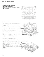
• This equipment will not guarantee the load ejection
operation when the mechanical unit is turned upside
down. In particular, if the ejection operation is incor-
rectly performed and recovery is disabled, the recov-
ery is enabled by resetting a product or turning ACC
off to on.
2) Test Mode
This mode is used for adjusting the CD mechanism
module of the device.
• Test mode starting procedure
Reset while pressing the 4 and 6 keys together.
• Test mode cancellation
Switch ACC, back-up OFF.
• After pressing the EJECT key, do not press any other
key until the disk is completely ejected.
• If the
]
or
[
key is pressed while focus search is in
progress, immediately turn the power off (otherwise
the actuator may be damaged due to adhesion of the
lenses).
• Jump operation of TRs other than 100TR continues
after releasing the key. CRG move and 100TR jump
operations are brought into the “Tracking close” sta-
tus when the key is released.
• Powering Off/On resets the jump mode to “Single
TR(91)”, the RF AMP gain setting to 0 dB, and the
automatic adjustment value to the initial value.
Содержание DEH-P6400
Страница 6: ...6 DEH P640 P6400 P6450 2 2 PACKING DEH P6450 13 18 16 1 11 15 17 10 9 8 14 4 6 7 5 2 3 12 ...
Страница 8: ...8 DEH P640 P6400 P6450 2 3 EXTERIOR ...
Страница 11: ...11 DEH P640 P6400 P6450 ...
Страница 12: ...12 DEH P640 P6400 P6450 2 4 CD MECHANISM MODULE D GEM1035 GEM1035 GEM1040 ...
Страница 36: ...36 DEH P640 P6400 P6450 A 1 2 3 4 B C D 1 2 3 4 A IC Q A TUNER AMP UNIT ...
Страница 37: ...DEH P640 P6400 P6450 5 6 7 8 A B C D 5 6 7 8 37 2 3 4 1 7 6 5 8 SIDE B A ...
Страница 41: ...41 DEH P640 P6400 P6450 1 2 3 4 A B C D 1 2 3 4 CLAMP 8EJ SIDE B CONTROL UNIT D D ...
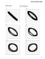
Страница 57: ...57 DEH P640 P6400 P6450 Grating waveform Ech Xch 20mV div AC Fch Ych 20mV div AC 45 0 75 60 30 90 ...


