20
CX-692
2. DISASSEMBLY
Precautions when making servicing works
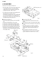
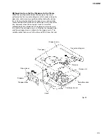
1) Since the upper surface of the arrowed magazine slot
in the DVD/CD mechanism unit can be deformed
comparatively easily, do not hold this section when
making servicing work. (Refer to Fig. 21.)
2) The stage mechanism projects downward beyond the
low end of the chassis when it is reset.
Consequently, the stage mechanism may be damaged
to cause functional failures when handled carelessly.
When placing the mechanism, pay great attention not
to damage the gear and the pickup unit.
-
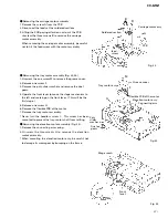
Removing the pickup unit
1. Set the short switch of the pickup unit to the SHORT
side.
2. Remove the flexible PCB from the connector.
3. Unscrew one screw A to remove the grease cover.
4. Unscrew one screw B to remove the plate spring A.
5. Unscrew one screw C to remove the plate spring B.
6. Remove the pickup unit together with the main shaft.
7. Remove the cushion from one side only to pull out
the main shaft. AT this time, pay attention not to lose
the removed cushion.
-
Removing the PCB unit(B)
1. Remove soldering from the linear position sensor
(VR301).
2. Unscrew the two screws D to remove the PCB unit(B).
-
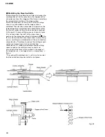
Precautions when installing the linear position
sensor
1. If the linear position sensor (VR301) is not being
properly inserted into the U-groove provided in the
detection lever, elevation movement failures can
occur.
When installing the linear position sensor to the
DVD/CD mechanism unit, be sure to insert it into the
U-groove provided in the detection lever securely.
Fig. 22
DVD/CD mechanism unit
Fig. 21
Short switch
Cushion
Cushion
Main shaft
Pickup unit
Plate
spring B
C
B
A
D
D
Plate
spring A
grease
cover
PCB
unit(B)
Soldering
VR301
U-groove
Detection lever


