


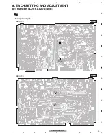


AXM-P90RS/EW5
18
1
2
3
4
1
2
3
4
C
D
F
A
B
E
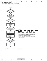
5. DIAGNOSIS
5.1 OPERATIONAL FLOWCHART
VDD1, 2 = 5 V
Pin 19, 41
Power ON
BSENS
Pin 93
ASENS
Pin 92
SWVDD L
Pin 1
ASENBO H
Pin 28
Source keys
operative
Completes power-on operation.
(After that, proceed to each source operation)
SYSPWR H
Pin 21
Starts
communication
with Grille
microcomputer.
Source ON
300 ms
300 ms
In case of the above signal, the communication
with Grille microcomputer may fail.
If the time interval is not 300 msec, the oscillator
may be defective.
Содержание AXM-P90RS/EW5
Страница 15: ...AXM P90RS EW5 15 5 6 7 8 5 6 7 8 C D F A B E ...
Страница 25: ...AXM P90RS EW5 25 5 6 7 8 5 6 7 8 C D F A B E ...
Страница 28: ...AXM P90RS EW5 28 1 2 3 4 1 2 3 4 C D F A B E 9 2 EXTERIOR A B C A B B C C A AXM P01_J 2_2 18 ...
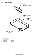
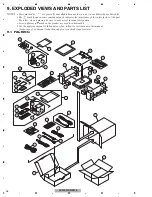
Страница 30: ...AXM P90RS EW5 30 1 2 3 4 1 2 3 4 C D F A B E 9 3 DISPLAY UNIT AND ACCESSORY D 18 AXM_P01_J 1_2 ...
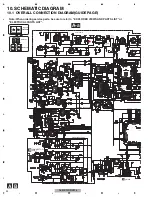
Страница 41: ...AXM P90RS EW5 41 5 6 7 8 5 6 7 8 C D F A B E D a D b D b 1 PD8176A TC74VHCT541AFTS1 MXK8203 L MODULE ...
Страница 42: ...AXM P90RS EW5 42 1 2 3 4 1 2 3 4 C D F A B E D b D a D a D b PD6573A S 818A33AUC BGN A JA801 ...
Страница 43: ...AXM P90RS EW5 43 5 6 7 8 5 6 7 8 C D F A B E D a D b D b D a 1 MXK8203 OEL MODULE ...


