background image

2018PC-03/03

11

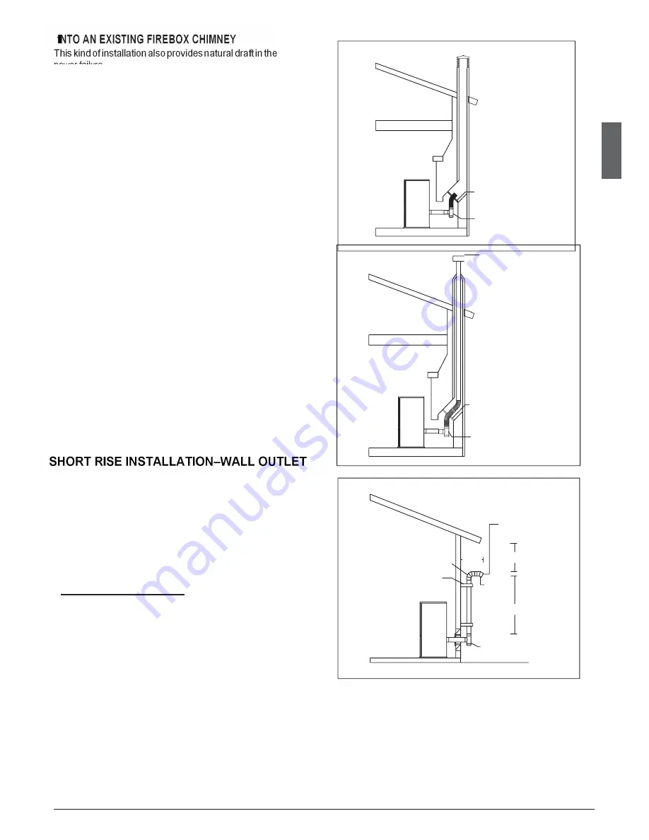
This kind of installation also provides natural draft in the event of a

power failure.

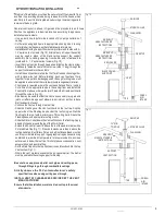
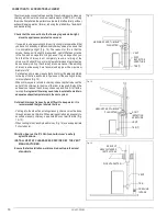
When installing as a hearth mount stove into a firebox the unit must

either be relined, terminating above the chimney chase top, or positively

connectedtotheexistingchimney systemusinga block offplate(Fig.

15-16).

An approved flex liner of PL vent must be used.

Putattention:someareasrequirethatalinermust bealwaysinstalled

to the top of the flue,as shown in figure 16.

A chimney system with known drafting problems may require

a liner, which may also need to be insulated to keep vent

system warm in cold chimney environment.

A cap shall be installed on the chimney to keep out rain.
Strictly observe the PL Vent manufacturer’s safety

specifications.

I

NSTALL VENT AT CLEARANCES SPECIFIED BY THE VENT

MANUFACTURER.

Strictly use listed pellet vent pipe fittings.
Ensure that all installation work is carried out to professional

standards

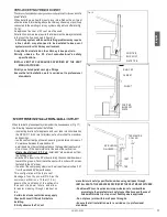
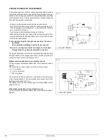
When terminating the exhaust system under the houses eaves,(Fig.17)
the following requirements shall be fulfilled:

- in selecting locations for appliance and vent, take into consideration

the NPFA 211 6-3.5 rule for distance of exit terminal from window

andopenings;

- runtheventverticallyupthewall,ensuringtomaintainaminimumof

3”clearancebetweenthewallandvent;

- a wall bandmust be installedjust above thetee andat least every6’

of vent rise or,if therise is inferior,at the end of the vertical run;

-

after a rise of at least 5’ (1.5 m)

,install a 90° elbow aimed out from

the building wall;

- attach a 45° elbow to the 90° elbow,aiming the second elbow down

toward the ground. Terminate the vent with a collar with screen

fastenedtothe45°elbow;

- the end of the vent pipe system must be at least twelve inches (12”)

fromthewalland24”below theeave.

This configuration will help prevent

blockage of vent by snow drifts. Also the

minimum vertical run of 5 feet (1.5 m)

ensures the ventilation of the exhaust in

the event of a power failure, and allow

for easier cleaning through cleanout on

tee.

-Certain local code restrictions may apply.

Check with Local Officials first before

installing.
-Strictly observe the PL Vent

manufacturer’s safety specifications when using wall pass through.

-INSTALL VENT AT CLEARANCES SPECIFIED BY THE VENT MANUFACTURER.

-Double wall PL vent requires a minimum clearance to combustibles

according to the manufacturer’s safety specifications and the use of

listed wall thimble, fire stop or roof flashing where applicable.

-Do not place joints within wall pass throughs.
-Ensure that all installation work is carried out to professional

standards.

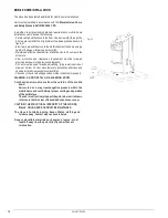
Fig. 15

POSITIVE

BLOCK OFF

PLATE TEE

Fig.

16

RAIN CAP

CHIMNEY

FLASHING

PLVENT

SYSTEM

POSITIVE

BLOCKOFF

PLATE

TEE

Fig.

17

TERMINATION

COLLAR

90° ELBOW

WALL BAND

>12

"

> 24"

45°

ELBOW

VENT

>5

'

TEE

En

gl

ish

Содержание PC-P03

Страница 1: ...1 Pellet Stove PC P03 INSTRUCTIONS FOR INSTALLATION USEAND MAINTENANCE The instruction manual is an integral part of the product English ...

Страница 2: ...oduct is to be installed is perfectly level When handling the steel parts of the cladding it is advisable to use clean cotton gloves to avoid leaving fingerprints that are difficult to removeatfirsttimeofcleaning The stove must be assembled by at least two persons Connectthepelletstovetotheelectricitysupplyonlyafterithasbeen connected by an expert to the flueway Theplugattheendofthepowercablemustb...

Страница 3: ...ination requirements 12 Prevention of domestic fires 13 Mobile home installation 14 TECHNICAL CHARACTERISTICS AND SPECIFICATIONS 15 Features 15 Technical data 15 Accessories and equipment 15 Product identification data 16 Dimensional diagram 16 Wiring diagram 17 3 0 FUEL 18 4 0 PREPARING FOR INSTALLATION 18 USE 19 Loading the pellets 19 6 0 PRODUCT AND CONTROL SYSTEM 20 Product overview 20 Control...

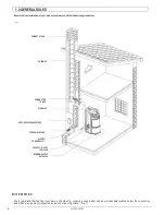
Страница 4: ...NECTION TO FLUE FLUEWAY SOOT INSPECTION APERTURE FRESH AIR INTAKE ELECTRIC POWER SUPPLY CAPACITY LOAD OF THE FLOOR MINIMUM SAFETY DISTANCES SOOT INSPECTION We recommend that the flue must have a chamber for collecting solid matter and any condensate located below the connection and which may be easily inspected by means of an airtight door Fig 1 English ...

Страница 5: ...ning Use an elbow or shield to prevent prevailing winds from blowing directly into the outside air intake pipe NOTE Mesh screen should be no smaller than 1 4 by 1 4 6 4 by 6 4 mm Outside combustion air is required for all mobile home installations and where building codes require In bedroom or bathroom installations the outside air connection is required Contact local building authority before ins...

Страница 6: ...ntofunitandbeyondeachsideof the fuel loading and ash removal opening 4 10cm from the external side of thecoating Connection to the flue must respect minimum safety distances from heat sensitive structural components or inflammable materials wood paneling beams or ceilings etc shown in figures The stove will become hot while in operation Keep children away from all stovesurfaces Direct contact with...

Страница 7: ...not connect to a flueway into which extractor hoods discharge vapours The very hot exhaust gases may cause skin burns keep a considerable distance away from the appliance Theexhaustgasesfromthecombustionofpelletsfuelmaydirtytheoutsideofthewalls Toavoidsuchpossibilityterminatethevent above the roofline Pipes and maximum usable lengths Theexhaustpipeon allstoves is 3 76 mm O D so the stove wasdesign...

Страница 8: ...ot whichbuildsupinsidethepipe Itmustalsopermitperiodiccleaningofthefluewithouttheneedto disassemble thepipes Single or double clean out tees may be used An example is given below of a flueway connection which allows complete cleaning without having to disassemble the pipes Fig 9 Fig 9 INSULATING MATERIAL SEE VENT MANUFACTURER S INSTRUCTIONS TEE DIRECTION OF CLEANING 0 10 TEE MIN 3 HMIN 13 H MIN5 D...

Страница 9: ... as necessary to jog around joists or rafters Keep use of elbows to a minimum as they reduce draftscapacityofavent Continue theVent up through the roof line Slide the Flashing over the Vent until it sits on the roof line Slip the upper side of the Flashing base under the roof shingles Nail the flashing to the roof with a minimum of 8 roofing nails Seals the Flashing base with appropriate roofing m...

Страница 10: ... areas require that a liner must be always installed to thetop of theflue asshown in figure even ifthe existing chimney is in compliance Fig 13 When chimneys are relined a chimney chase cap thatreduces the outlet of the chimney to the size of the liner is required Extend the exhaust vent above the chimney chase cap and finish it off with a raincap Asinglewalllinermayneedtobeinsulatedtomaintain ade...

Страница 11: ...nthewallandvent awallbandmustbeinstalledjustabovetheteeandatleastevery6 ofventriseor iftherise isinferior attheendoftheverticalrun after a rise of at least 5 1 5 m installa 90 elbow aimedoutfrom the building wall attacha45 elbowto the90 elbow aimingthesecondelbowdown toward the ground Terminate the vent with a collar with screen fastenedtothe45 elbow theend ofthe ventpipe system must be atleasttwe...

Страница 12: ...red Be sure to use approved pellet vent pipe and wall pass through fittings to go through combustible materials The type of installation must first be considered before determining the exact location of the venting termination in relation ship to doors window cavities or air vents See figures 18 19 Without outside combustion air connected to the unit For These types of installations please refer t...

Страница 13: ...linstallation work iscarried out to professional standards PREVENTION OF DOMESTIC FIRES The product must be installed and used in compliance with the manufacturer s instructions and national standards as well as local regulations When a flue pipe passes through a wall or a ceiling special installation methods must be applied protection thermal insulation distances from heat sensitive materials etc...

Страница 14: ...ous paragraphs PL Vent must be used for exhaust venting Single wall vent is not allowed Follow PL Vent manufacturer s installation directions and observe all listed clearances to combustibles Check any other local buildings codes or other codes that may apply WARNING DO NOT INSTALL IN A SLEEPING ROOM Combustion air must come from the outside of the mobile home Failure to do so may create negative ...

Страница 15: ...DATA model PC P03 Heat input kW h 6 11 Pellet consumption per hour kg h 0 6 2 2 Overall efficiency 90 Rated current during ignition A 1 2 Maximum power input during ignition W 248 Maximum power input at work W 68 Electrical power supply voltage V 230 Rated frequency Hz 50 Fuel tank capacity kg 21 Fuel size mm D6 8 L10 40 Exhaust outlet diameter mm Ø 76 Max heating area m 110 Weight with cladding k...

Страница 16: ...2018PC P03 03 16 DIMENSIONAL DIAGRAM Fig 22 Unit mm ...

Страница 17: ...2018PC 03 03 17 WIRING DIAGRAM Fig 23 ...

Страница 18: ...d be stored in a sheltered dry place To use good quality pellets with dimensions and heat producing properties other than those recommended above it will be necessary to change the stove operating parameters The useofcordwood is prohibited Do notburn garbage or flammable fluids such as gasoline naphtha or engine oil This customisation ofstovesettingsmustbecarriedoutby authorisedpersonnelbydistribu...

Страница 19: ...any hot surfaces Operate this unit only with the fuel hopper lid closed Failure to do so may result in emission of products of combustion from the hopperunder certain conditions Maintain hopper sealingood condition LOADINGTHEPELLETS When lighting your stove for the first time or any time you have run out of Pellets you will need to fill the hopper Pellets are fed from the hoppertotheburnpotbyanaug...

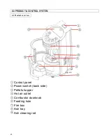
Страница 20: ...20 6 0 PRODUCT CONTROL SYSTEM Control panel Power switch back side Pellets hopper Hot air outlet Combustor doorknob Feeding hole Fire box Ash tray Ash cleaning rod 6 1 Product overview Fig 24 ...

Страница 21: ...ing program click to on or off Setting temperature Click and press to set the temperature Room temperature Setting button click to enter the setting page Current fire level Quick timing press to set Minus and plus button for setting the temperature and quick timing 6 2 Controller Main page Fig 25 ...

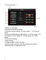
Страница 22: ...al mode Press for pellet feeding speed setting 3 is 100 speed 2 is 75 speed 1 is 50 speed 4 is 125 speed 5 is 150 speed Current time setting Week setting Timing program click to entering Factory model click and input the password to entering Number plate for setting the value Fig 26 6 3 Control system Setting ...

Страница 23: ...ek then click save Auto boot time 24 hours per day Run time For example run two hours and three minutes then input 02 30 into the form Stage click to change four stages for one day the boot time should not be earlier than the Number plate for setting the time 6 4 Control system Timing Fig 27 ...

Страница 24: ...value is 1 Fig 31 Fig 31 5 FEED1PR FEED4PR Setting the feeding period time for fire level 1 4 the default value is FEED1PR 5 FEED2PR 4 FEED3PR 3 FEED4PR 2 Fig 32 6 FAN1 FAN4 setting the hot air blower fan for fire level 1 4 the default value is FAN1 15 FAN2 20 FAN3 25 FAN4 35 Fig 32 Fig 32 20 Setting the auto ash cleaning time For example Auto clean the ash in every 4 hours Fig 33 Fig 33 21 Settin...

Страница 25: ... replacing NTC room temperature sensor Fig 56 10K 2 Display shows E2 the flame sensor is missing or broken please replacing the K type flame sensor Fig 57 3 Display shows E3 the pellet hopper is empty please refuel 4 Display shows E4 the burning grate is not in the right place please replace it 5 Display shows E5 the pressure of burning chamber is not normal please close all the parts of this stov...

Страница 26: ...ber and ash tray in a regular time If the ash tray is full the stove will stop to work Fig 36 Fig 36 2 Cleaning the ash from the heating tube in the regular time Fig 37 3 Opening the side plate and cleaning the inside ash in the regular time Fig 37 ...

Отзывы: