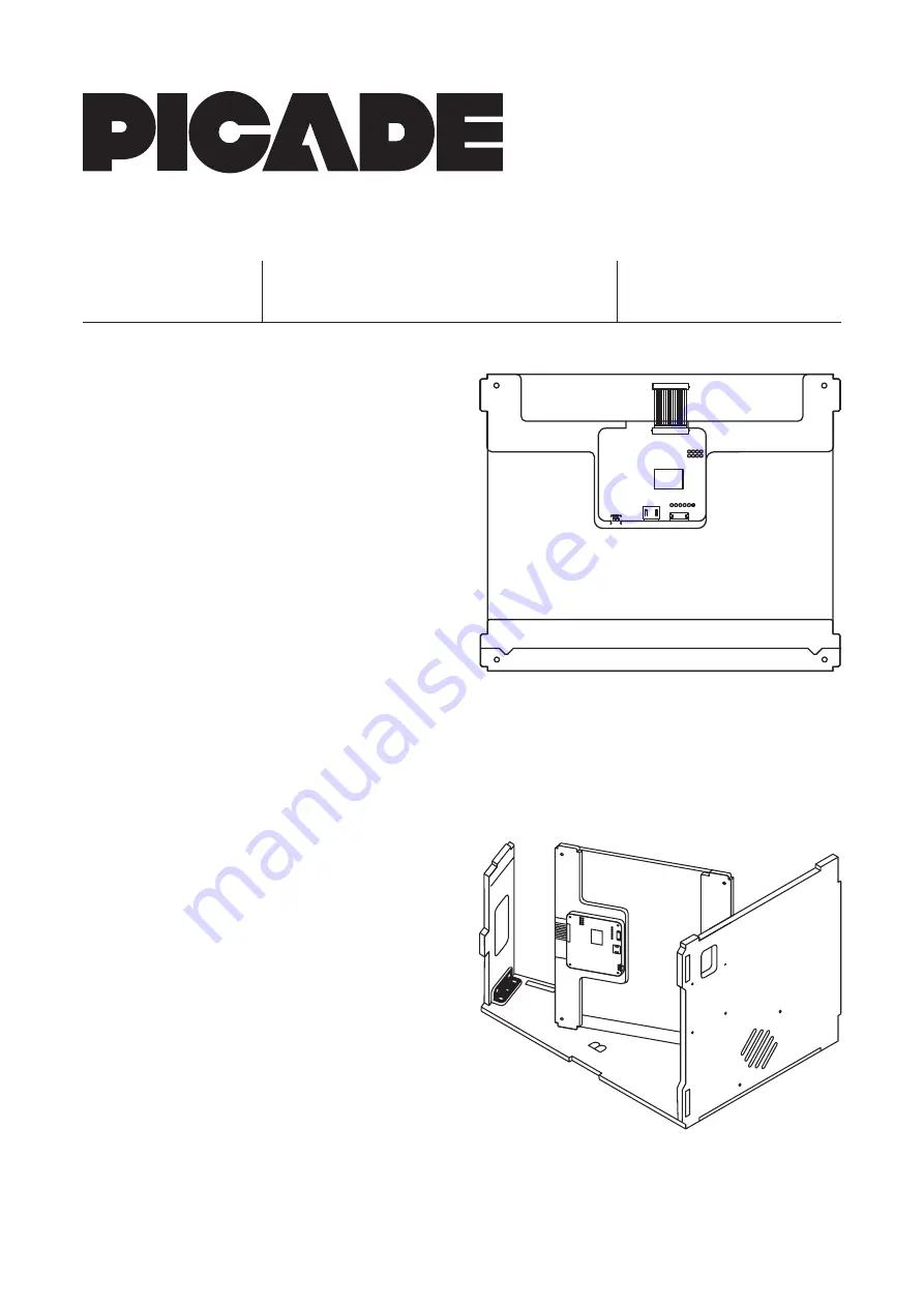
2. Building the Screen
Open the SCREEN box, containing the screen and associated bits.
The acrylic that goes in front of the screen is the large, approximately
square piece that is in the CABINET box.
All of the acrylic pieces, including the screen acrylic, will have white
protective film on. Peel this off each of the pieces as you use them.
Take the screen acrylic and lay it down with the tabs on either side.
Lay the black card screen surround on top, with the tabs aligned with
the acrylic piece. The narrower edges should be at the left and right.
One of these sides is very slightly narrower than the other (~6mm vs.
~5mm), and the narrower side should be laid at the left hand side.
Place the narrow acrylic piece that says BASE 1 at the base of the
screen assembly, so that the text is readable as you look at it.
Peel the protective film off the screen, and place it onto the screen
assembly, so that the metal tabs fit into the v-shaped slots on the BASE
1 piece, and the connector is towards the top edge.
Before adding the final parts of the screen assembly, attach the display
driver board to its acrylic bracket. Take the acrylic piece (marked TOP 2),
and place it with the protruding part pointing downwards. Push four
M2.5 bolts through from the back of the acrylic, and then attach the
driver board with four M2.5 nuts, making sure that the HDMI and
micro-USB ports are towards the base, and the ribbon cable connector
is towards the cutout at the top.
Note that the top part of the 10” screen assembly is not held together
with nuts and bolts, but will be held in place by the tabs and slots once
the cabinet is screwed back together. You might want to use a couple
of pieces of masking tape to hold things in place until you get the
cabinet back together.
Place the acrylic piece marked BASE 2 at the base of the screen
assembly, so that the BASE 2 text is readable. Place the TOP 2 bracket
with the driver board towards the centre of the screen. We’ll fit the
whole assembly into the cabinet before connecting the ribbon cable.
Lay the keypad and cable aside for later.
Slot the whole screen assembly into the side of the casing that you’ve
assembled. The driver board should be closest to the top of the cabinet.
Move onto ‘Section 3. The marquee’ now, and fit the marquee, and
secure the whole cabinet together to hold the screen assembly in place.
Take the ribbon cable, and hold it with the blue end facing upwards.
Gently flip up the black clip on the driver board, slot the blue end into
the connector and push the clip down again. The other end of the cable
with the metal connector clicks into the connector at the top of the
display. Use a fingernail to make sure that it’s pushed all the way in.
You may now return to the main instruction sheet and carry on.
This sheet replaces the whole of ‘Section 2. Building the screen’
on the colour instruction sheet, so please use the instructions
on this sheet in place of that section!
UPGRADING?
If you’re upgrading an existing Picade,
see the other side first.
NOTE!
10” screen addendum
2019.01.03
C:/Users/PiratePete/Arrr/Shiny/Picade10InchUpgrade.pdf
© 2018, 2019 Pimoroni Ltd.


