


Inbetriebnahme
Beachten Sie bei der Inbetriebnahme:
• Die Ausgangskontakte 11-12-14 und
21-22-24 sind Hilfskontakte (z. B. für
Anzeige oder Schützansteuerung).
•
Vor die Ausgangskontakte eine Siche-
rung (6,3 A flink oder 4 A träge)
schalten, um das Verschweißen der
Kontakte zu verhindern.
• Leitungsmaterial aus Kupferdraht mit einer
Temperaturbeständigkeit von 60/75 °C
verwenden.
• Das Anzugsdrehmoment der Schrauben
auf den Anschlußklemmen darf max.
0,8 Nm betragen.
• Angaben im Kapitel "Technische Daten"
unbedingt einhalten.
Anschluß
• Betriebs- bzw. Meßnennspannung mit
Wahlschalter einstellen.
• Ansprechwert U
min
am unteren Potentio-
meter und Ansprechwert U
max
am oberen
Potentiometer mit Hilfe eines kleinen
Schraubendrehers einstellen.
• Betriebs- bzw. Meßnennspannung an die
Klemmen A1 (+) und A2 (-) anlegen.
• Ausgangskontakte entsprechend der
jeweiligen Anwendungsschaltung anschlie-
ßen.
Ablauf
Liegt die Betriebsspannung zwischen den
Ansprechwerten U
min
und U
max
, sind die
Kontakte 11-14 und 21-24 geschlossen und
die Kontakte 11-12 und 21-22 geöffnet.
Überschreitet die Betriebsspannung den
Ansprechwert U
max
oder unterschreitet sie
den Ansprechwert U
min
, öffnen die Kontakte
11-14 und 21-24 und die Kontakte 11-12 und
21-22 schließen. Die LED "FAULT" leuchtet.
Anwendung
Das Gerät nur wie im folgenden An-
schlußbild anschließen.
Mise en oeuvre
Remarques préliminaires :
• Les contacts de sortie 11-12-14 et 21-22-
24 sont des contacts d'information (ex.
pour signalisation ou pilotage de relais).
• Protéger les contacts de sortie par des
fusibles (6,3 A rapides ou 4 A normaux)
pour éviter leur soudage
• Le couple de serrage sur les bornes de
raccordement doit être d'au max. 0,8 Nm.
• Utiliser des câbles en cuivre supportant
des températures de 60/75°C
• Respecter les données indiquées dans le
chapitre „Caractéristiques techniques“.
Branchement et réglage
• Sélectionner la tension d'alimentation à
l'aide du commutateur
• Régler les seuils mini U
min
et maxi U
max
à
l'aide d'un petit tournevis
• Ramener la tension d'alimentation (circuit
de mesure) sur les bornes A1 (+) et
A2 (-)
• Câbler les contacts de sortie suivant le
fonctionnement désiré
Mise en oeuvre
Si la tension d'alimentation est comprise
entre les seuils U
min
et U
max
, les contacts
11-14 et 21-24 sont fermés et les contacts
11-12 et 21-24 sont ouverts.
Si la tension surveillée dépasse le seuil U
max
ou passe en dessous du seuil U
min
, les
contacts 11-14 et 21-24 s'ouvrent et les
contacts 11-12 et 21-22 se ferment.La LED
"FAULT" s'allume.
Operation
Please note with operation:
• The output contacts 11-12-14 and 21-22-
24 are auxiliary contacts (eg. for signalling
or contactor control)
• To prevent contact welding, a fuse (6,3
A quick or 4 A slow) must be
connected before the output contacts
• Use copper wires that can withstand
temperatures of 60/75 °C
• Tighten terminals to a max. 0.8 Nm
• Important details in the section “Technical
Data” should be noted and adhered to
Connection
• Set operating voltage / measuring nominal
voltage with the rotary switch
• Using a small screwdriver set the
response value U
min
on the lower
potentiometer and the response value
U
max
on the upper potentiometer
• Connect operating voltage / measuring
nominal voltage to terminals A1 (+) and
A2 (-)
• Connect the output contacts according to
the application.
To operate
If the operating voltage lies between the
response values U
min
and U
max
, the contacts
11-14 and 21-24 are closed and the contacts
11-12 and 21-22 are open. If the operating
voltage exceeds the response value U
max
or
falls below the response value U
min
, the
contacts 11-14 and 21-24 open and 11-12
and 21-22 close. The LED “FAULT” is
illuminated.
Application
Connect the unit according to the
following diagram.
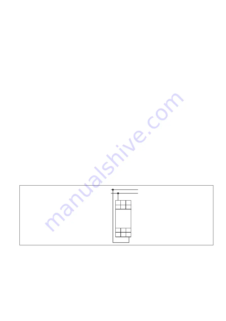
Fig. 3: Anschlußbild
Connection diagram
Schéma de branchement
22 24 A2
A1 11 21
1L1
1L2
U
M
= U
B
12 14
Überprüfung - Fehlerursachen
Die Spannungsüberwachungsrelais reagie-
ren nicht auf den eingestellten Spannungs-
wert, falls
• der Meßkreis unterbrochen oder kurzge-
schlossen ist
• die Betriebsspannung U
B
ausgefallen ist
• ein Defekt am Spannungsüberwachungs-
relais selbst vorliegt.
Test - Sources d'erreur
Le relais ne réagit pas aux seuils réglés en
cas de :
• coupure ou mise en court-circuit du circuit
de mesure.
• non présence de la tension d'alimentation
• défaut interne du relais de tension
Testing - Fault Causes
The voltage relays do not react to the set
voltage value if:
• The measuring circuit is interrupted or
short-circuited
• Operating voltage U
B
fails/drops out
• There is a defect in the voltage monitoring
relay itself.
Utilisation
Le relais doit être câblé uniquement
comme indiqué dans le schéma ci-
dessous.